


PCIe/PXIe-5211 |
| 18
To cofigure the pause trigger, use the properties as below:
JY5211CITask.EdgeCounting.Pause.ActivePolarity – To set active level (high or
low) to pause counting.
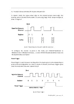
Count Direction
User can control the counting direction through software configuration or by an
external input signal. Default, the external control direction signal must be
connected to Counter Aux terminal.
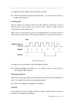
When using an input signal to control the counting direction, the counter counts up
when the signal is high and counts down when the signal is low as shown in Figure 9.
Figure 9 Count Direction
To cofigure the count direction, use the properties as belows:
JY5211CITask.EdgeCounting.Direction – To specify count up, count down, or
controled by an external signal.
Exporting Count Event
When the counting value reaches the specified threshold, the counter will generate a
pulse. To change the threshold, using following property:
JY5211CITask.EdgeCounting.OutEvent.Threshold
Terminals
To change the terminal of signals instead of using its default value as shown in
chapter 2.6, using following properties:
Summary of Contents for PCIe-5211
Page 9: ...PCIe PXIe 5211 jytek com 5 2 2 Digital IO Specifications Table 1 Digital IO Specifications...
Page 11: ...PCIe PXIe 5211 jytek com 7 2 4 Other Specifications Table 3 Other Specifications...
Page 12: ...PCIe PXIe 5211 jytek com 8 2 5 Front Panel and Pin Definition Figure 3 Front Pannel...
Page 13: ...PCIe PXIe 5211 jytek com 9 Table 4 Pin Defination...
Page 36: ...PCIe PXIe 5211 jytek com 32 Figure 24 Frequency Measure Values In Single Mode...