background image

57

Problem:

“Unable to Open Serial Port” message

The JW Fishers Sonar requires a COM (serial) port to pass operation parameters from the

PC to the Sonar.  It will be necessary to configure the JW Fishers Sonar software to open the
correct COM (serial) port for communications.  Below are instructions for configuring the COM
(serial) port.

To select the COM (serial) port number that the software will use:

1. Cable and power up the JW Fishers Sonar system.  Do not launch the JW Fishers

Sonar application at this time.

2. Select the Windows ‘Start’ menu and single right mouse click on ‘My Computer’.
3. A pop-up menu will appear.  Left mouse click on ‘Manage’
4. Left mouse click on ‘Device Manager’ (found in the left hand list).
5. In the Device Manager window a list of your computers hardware will be shown.  Click on

the ‘+’ symbol next to ‘Ports (Com & LPT)’.  If this is not shown, make sure the Sonar
Processor power is ON and the Sonar Processor is connected to the PC with a USB
Cable.

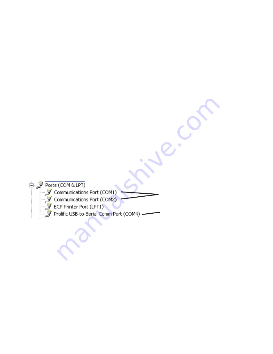
6. After clicking on ‘Ports (Com & LPT), one or more items will be shown. Look for the item

that refers to your USB to Serial Adapter, it will be something like ‘Prolific USB to Serial
Com Port (COM4)’ or ‘Belkin Serial Port (COM6)’. Note which COM port number has
been assigned to the USB to Serial Adapter.

7. Close all open windows.
8. Launch the JW Fishers Sonar application
9. A message box will appear stating “Unable to Open Serial Port.  Select Cancel to work

Offline”.  Select “Cancel”.

10. Open the “Settings” Menu and select “Select Serial Port Number”
11. Select the COM port number that matches the COM port number found in step 6.  (If

more than one COM port was listed, try each one until you find the one that works.)

The JW Fishers Sonar COM settings are now configured.

*Note:
If the USB to Serial Adaptor is installed in a different (physical) USB port, the COM port

number changes and you will have to repeat these steps to reconfigure the COM settings.

Hardware COM Ports

USB to Serial Adaptor

(USE THIS ONE)

Troubleshooting

Summary of Contents for SSS-100K PC

Page 1: ...E SCAN PC OPERATION MANUAL JW FISHERS MFG INC rev 071211 USB JW FISHERS MFG INC 1953 COUNTY ST E TAUNTON MA 02718 USA 508 822 7330 800 822 4744 FAX 508 880 8949 Email jwfishers aol com WEB www jwfishers com ...

Page 2: ...2 SSS 100K PC SSS 600K PC SSS 100K 600K PC SIDE SCAN SONAR OPERATION AND MAINTENANCE MANUAL 1953 COUNTY STREET EAST TAUNTON MA 02718 JW FISHERS MFG INC ...

Page 3: ...E SCAN SONAR 12 JW FISHERS SIDE SCAN SONAR THEORY OF OPERATION 14 OPERATORSWITCHESANDCONTROLS 25 INSTALLINGHARDWAREANDSOFTWARE 40 CABLINGTHESYSTEM 47 OPERATION 49 SAMPLE PLAYBACK 50 SAMPLERECORDING 52 FAQs 56 TROUBLESHOOTING 57 APPENDIX A configuring GPS 59 APPENDIX B USB to Serial Adaptor 60 MAPPINGOPTION 62 ADJUSTABLETRANSDUCEROPTION 72 MAINTENANCE 74 WARRANTY 74 TABLE OF CONTENTS ...

Page 4: ...ect a wire from the Water Ground terminal on the Sonar Processor panel directly to a piece of metal that goes into the water Loosen the thumbscrew next to handle one turn to prevent pressure buildup inside the Sonar Processor housing Protect fish fins when fish is out of water Insure lower fins are protected Pile tow cable on deck and sit fish on top of tow cable pile Protect cable end connectors ...

Page 5: ... Processor 13 Wx10 Hx6 D 8 lbs Cable 75 x150 500 25 85 lbs Fish 4 D x 62 L 35 lbs Shipping boxes Sonar Processor Fish 150 1 000 ft 67 Lx16 25 Dx19 24 H 150 445lbs MATERIALS COLOR Sonar Processor High impact plastic case PVC stainless black Fish High impact PVC epoxy stainless yellow Cable 10conductorinpolypropylene yellow OPTIONS Extra cable up to 1 000 ft 120 vac to 12 vdc wall power supply 220 v...

Page 6: ... 600MHz System memory 128 Mb RAM 256 Mb Ram minimum recommended for Windows XP Video Card capable of 32 Mb Video memory 16 bit color Minimum Screen Area of 800 x 600 pixels 1024 x 768 recommended One available USB port Windows 98 or later 40 Mb of free disk space for program installation Disk space for file recording SONAR VIEW uses up to 500 Mb per hour when recording highest quality images in sh...

Page 7: ...rent size targets when doing a general search Once atargetisdetected theRangesettingwouldbereduced andcloserpassestothetargetwouldbemadeandatdifferent angles The closer passes at shorter Range settings produce the best pictures More detail is shown on the computer screen when operating in the short ranges The above recommended ranges are conservative A 75 boat recommended range 200 m could be pick...

Page 8: ...urns to the transducer the transducer is mechanically excited by the sound pressure wave and converts the vibration into an electrical signal This signal is then detected and amplified by the receiver The control display unit regulates the precise timing between the transmitter receiver and display elements DEPTH SOUNDER Depthsoundersareasimpleformofsonar Theysendoutaconicalshapeenergypulsetowardt...

Page 9: ...ed in any water depth so it can be close to the target which produces the most detail PC Monitor A side scan sonar display builds up its image by laying down successive scans of the sonar image producing a composite image To achieve high resolution side scan reduces the beam width to a narrow 1 to 2 deg and the transducer is mountedonatowedfishdesignedforstability Wavesandarockingboathaveverylittl...

Page 10: ...eflected away from the fish When the bottom slopes away and down from the fish only light echo s return from the bottom When the bottom slopes upward medium echo returns are received If a hard target is positioned on a down or on a up sloping bottom a hard return will result from the target If a target is up off the bottom as is target 1 and 2 then there will be an area directly behind the target ...

Page 11: ... therefore less resolution The target will be displayed at one half the vertical height In the figure below we left the Range Switch setting at 50 m but cut the boat speed in half The result is that we get the same resolution as the top figure while covering twice the scan distance Boat speed is important slower boat speeds produce the highest resolution images Note Ideal towing speed is 1 knot So...

Page 12: ...tronicsthroughthewater It iscritical for good printouts that the fish tows stable through the water stable not perfectly straight If the fish is towed cross current across a river the fish will actually tow pointed slightly upstream This is due to the water flow pushing against the fins This will not cause a problem with the printout The printout is effected when the fish is not stable while under...

Page 13: ...information on the screen moves down one line and the new information is displayed in the top line the oldest line at the bottom drops off the screen The process is repeated indefinitely 123456789012345678901 123456789012345678901 123456789012345678901 123456789012345678901 123456789012345678901 123456789012345678901 123456789012345678901 123456789012345678901 123456789012345678901 123456789012345...

Page 14: ...5678901 123456789012345678901 123456789012345678901 123456789012345678901 123456789012345678901 123456789012345678901 123456789012345678901 123456789012345678901 123456789012345678901 123456789012345678901 123456789012345678901 123456789012345678901 123456789012345678901 123456789012345678901 123456789012345678901 123456789012345678901 123456789012345678901 123456789012345678901 123456789012345678...

Page 15: ...ine all lines on the screen move down one to allow room for the next line While the above displaying took place the CPU sent another transmit pulse to the fish This sequence repeats itself for as long as the side scan is turned on Each transmit pulse results in one line being displayed in each channel Both channels are displayed simultaneously How often we transmit depends on the Range selected Th...

Page 16: ...pictures Closetothetransducer isaverybroadbeamwhichistheresultofsidelobes Allsidescantransducers have side lobes Top quality transducers such as those used in the JW FISHERS Side Scan Sonar have very short side lobes which extend a very short distance Poor quality transducers have long side lobes extending 20 30 of the total beam length Theimpactofsidelobesisthattheprintedpicturewillbedistortedift...

Page 17: ...m is 40 deg wide The transducer is tilted pointed 10 deg down to insure that the main impact of the beam will sweep across the bottom The main power of the beam is in the dark shaded area The lightly shaded area shows the secondary area of the beam It lacks the power of the main part of the beam but is part of the overall vertical beam pattern and does detect targets T R A N S D U C E R Right Main...

Page 18: ...e fish is close to the surface the echo reflections from the waves will be visible on the display The drawings below show the effect of surface targets when the fish is close to the surface All of the targets shown above will be picked up and displayed as shown below Drawing assumes targets are in a straight line water column factor not included covered later The displayed position of target 4 is ...

Page 19: ...or Wires To Surface Control Box Transmit Circuitry Pre Amp Transmit Pulse From control box Signals To Control Box Transducer Sonar Processor Sonar Processor Sonar Processor FISHELECTRONICS The fish contains a underwater housing that contains the electronics to generate the 1000 watt power pulse to each transducer and preamps to amplify the returning echoes received by the transducers The amplified...

Page 20: ...arget 1 Target 2 Display if no TVG Fish 100 m 10 m Target 1 Target 2 Acoustic Wave 100 m Range Switch The signal return shown below to the Sonar Processor is the signal that we would expect to see at the output of the fishpreamps TheamplitudeofthesignalthatreachestheComputerdeterminesthecoloroftheimage IftheTVGcircuit did not modify the signal shown below Fig 2 then the display would start out goo...

Page 21: ...ng above applied to the input When this signal is printed there will be a even color across the paper with two dark colors representing the two targets fig A fig C Print Head Right Channel Target 1 Target 2 Display A m p l i t u d e Next transmit pulse Transmit pulse 1 2 Shadow Shadow G a i n Next transmit pulse Transmit pulse Low Gain High Gain A m p l i t u d e 1 2 Transmit pulse 8 Next transmit...

Page 22: ...art of the sweep Far Gain Adjusts the TVG gain at the finish Operator adjusts for even color of the displayed line Overall Gain Adjusts the gain of the complete line up or down It adjusts overall darkness or lightness Note Theanalogsignalbelow forboththeleftandrightchannels isvisibleonthedisplaysotheoperator can be viewing the analog signal while making the TVG adjustments The goal is to have a re...

Page 23: ...offthebottom andhigh enough off the bottom to insure the beam makes it out to the distance selected by the Range setting Ifbottomconditions trees debris etc donotallowthefishtobetowed10 15 offthebottom thenasignificantamount of display space may be wasted just waiting for the acoustic wave to reach the bottom If bottom conditions required the fish to be towed 10 m off the bottom and we are operati...

Page 24: ... Case Computer The system will run on a Laptop Desktop or on JW Fishers optional Splash Proof computer The Splash Proof is acomputersystemthatisbuiltintoaUnderwaterKineticscase Itutilizesa10 UltraBright displaywhichismucheasier to read in a open boat ...

Page 25: ...ight channel right side transducers on the side scan fish and the other set for the left channel the left side transducer on the side scan fish The Near Gain Far Gain and Overall Gain controls are adjustments for the Time Variable Gain TVG amplifier The function of these controls is to adjust the amplifiers to compensate for signal losses that occur when the signal travels through the water When t...

Page 26: ...ilable USB port at the computer Note It is best to use the same USB port every time you operate POWER INPUT The input power for the Sonar Processor is 12 volts dc A power cable is supplied with the side scan system One end of the cable connects to the Sonar Processor The end with red and black alligator clips connects to a 12 volt bat tery An optional 120 vac to 12 vdc wall transformer is availabl...

Page 27: ...sonar file Note Press ing the F1 key will also record a new sonar file Open file for playback Open an existing sonar file Record highlights to new file Records a portion of the existing sonar file to a new file See page 29 for more details Save screen as a picture Saves the image on the sonar screen as a Bitmap file Print Screen Prints the sonar image shown on the monitor Print Preview Shows how t...

Page 28: ... should be observed while adjusting the TVG amplifiers signal should be flat along its length Range Ruler Puts range marks on the monitor which allow the operator to easily determine the distance between any target and the towfish i e the boat View All Annotations Opens a dialog that shows all text annotations in the current file Actions The commands shown under theACTION pulldown menu duplicate m...

Page 29: ...ine to draw a bottom tracking line on image a Select Line color 4 The Threshold control 0 100 determines the minimum intensity signal used to calculate the bottom return 20 is a good starting point 5 Blanking Distance sets the point which Sonar View starts looking for the bottom return This skips past transducer transmitting propeller wash and close surface returns 2 meters is a good starting poin...

Page 30: ...to turn this setting off to get the best sonar image Frequency 100 Khz Operator selects which frequency Fish is being used If dual frequency Fish the operator selects which frequency to operate Frequency 600 Khz Operator selects which frequency Fish is being used If dual frequency Fish the operator selects which frequency to operate Help Help Topics Refers you to Operators Manual for help Com pany...

Page 31: ... right side sonar images 16 Left Window shows left side sonar image only 17 Right Window shows right side sonar image only 18 Sonar Coverage Map shows the optional sonar coverage map window 19 Zoom enlarges object see page 31 for more details 20 Measure size sizes the object see page 31 for more details 21 Measure Target Height opens the measure target height tool 22 View Annotations Displays a li...

Page 32: ...you want to measure b Press and hold the left mouse button c Drag the cursor to the bottom of the object you want to measure d Release the left mouse button In the upper left corner of the Zoom window is a File pulldown menu The options under the file pulldown menu are MEASURE SIZE There are two ways to determine the size of a object 1 Use the Standard toolbar size button a Click on the Measure Si...

Page 33: ...alks you through measuring the target height The current step required to measure the Target height is high lighted in black text All other instructions are grayed out As you completed one instruction that instruction is grayed out and the net instruction is highlighted in black text The target height will be displayed in the box at the bottom of the Measure Target Height Dialog Three markers will...

Page 34: ...to Click Target on Screen a Move the mouse pointer over the target you wish to attach the annota tion to and click the left mouse button The Latitude Longitude and ping number are automatically captured for the annotation record Creating New Annotations Annotations can be added during recording or during playback You can cre ate new annotations by clicking the Create New Annotation toolbar button ...

Page 35: ...e target up to 185 characters b At this time if you use the Measure Distance tool or the Measure Target Height tool the Distance and or Target Height will be automatically en tered into the description text 5 Now click a The Save Annotation button to save the annotation to the file b Or click the Save and Capture Image button i The Save and Capture Image button captures a bitmap image of the sonar...

Page 36: ...o jump to the Annotation place in the sonar image file click the Jump to Note button The sonar image file is automatically advanced to the annotation record in the sonar image file and displayed on the screen If an image was stored you can view the stored image by selecting the View Image button If an image was not stored the View Image button is hidden and replaced with a Capture Image button You...

Page 37: ...off an Annotation on the list you can then view the details of the annotation by clicking the View Details button or jump to the Annotation place in the sonar image file clicking the Jump to Note button If you wish to generate a text file containing all of the Annotation information in a sonar image file click the Generate Annotation report button These methods will open the Annotation Wizard Anno...

Page 38: ...text to be edited b The Jump to Note and View Capture Image buttons are replaced with Save Changes and Discard Changes buttons 2 Make changes to the Name or Description 3 When you are finished editing a Click the Save Changes button to save the changes you have made b Click the Discard Changes button to discard the changes you have made NOTE Changes are not saved until the Save Changes button is c...

Page 39: ...oming from the towfish and shown as the sonar image on the left side of the monitor The shade of the colors on the screen change as the gain changes The gain can be adjusted from 10 to 10 in one digit increments by clicking on the up or down arrows on the right hand side of the box showing the gain number Right gain Increases or decreases the size of the signal coming from the towfish and shown as...

Page 40: ...e and software installation optimize the perfor mance of your PC To optimize the performance of your computer for running SONAR VIEW software it is recommended that the user not allow MS Windows to control the performance of the computer Instead the user should set up the com puter for best performance TO SET YOUR COMPUTER FOR BEST PERFORMANCE DO THE FOLLOWING Windows 7 1 Click on the Windows STAR...

Page 41: ... battery When the sonar is actively scanning you may not touch the PC for quite some time To prevent the Screen Saver from activating or the PC going into Sleep Mode set the Poer Management settings as shown below TO DISABLE SCREEN SAVERS AND CONFIGURE POWER MANAGEMENT SETTINGS DO THE FOLLOWING 8 Click on the Windows START button on the lower left corner of the screen 9 Click on Control Panel 10 D...

Page 42: ...tep 5 4 If the SONAR VIEW banner box does not open within 60 seconds the installa tion can be performed from Windows Explorer A Open Windows Explorer from the Start Programs menu B Select JWF SONAR VIEW Click on Setup exe This will start the installa tion program 5 A message box will open stating windows is configuring InstaCal InstaCal will automatically install 6 After the InstaCal installation ...

Page 43: ...shers Sonar View to take effect Click on Yes I want to restart my computer now and OK to complete the InstaCal installation 17 Remove the Installation CD from the drive now 18 While the PC is rebooting follow the instructions in the Sonar Processor cover to cable and power up the Sonar Processor Do not plug the USB cable from the Sonar Processor into your PC at this time 19 Once Windows is fully l...

Page 44: ...Before the SONAR VIEW can be used for the first time this program must be run to configurethe Interface board which is integrated into the Sonar Processor This program must also be run whenever the Sonar Processor is used with a different PC The SP to PC interface USB Cable must be connected before running this program 1 From the Start menu select Programs Measurement Computing InstaCal 2 The Inst...

Page 45: ...onnected to the PC with a USB Cable 6 After clicking on Ports Com LPT one or more items will be shown Look for the item that refers to your USB to Serial Adapter it will be something like Prolific USB to Serial Com Port COM4 or Belkin Serial Port COM6 Note which COM port number has been assigned to the USB to Serial Adapter 7 Close all open windows 8 Launch the SONAR VIEW application 9 A message b...

Page 46: ...program 7 The Welcome to JW Fishers SONAR VIEW Setup Wizard box opens Click Next to continue 8 The customer information box opens Enter your name organization and the software serial number provided by JW Fishers Click Next 9 The Confirm Installation box opens Click Next 10 The Select Installation Folder box opens The default folder is C Program Files This should only be changed if either the Wind...

Page 47: ...ace Sonar Processor Fish PC Boat s GPS Step 1 Attach the tow cable from the side scan towfish to the Sonar Processor box Step 2 Attach the SP to PC interface USB cable from the Sonar Processor to an available USB port on the computer Note Always use the same USB port when operating the Side Scan Sonar This will eliminate the need to change communications settings SP to PC interface USB cable SP to...

Page 48: ...quires 12 volts dc Aseparate battery that is not connected to the boat s electrical system should be used to power the Sonar Processor If only AC power is available the sonar processor can be powered by the supplied ac power supply which converts 100 240vac to 12vdc If you are using the optional Splash proof ultrabright PC The optional Splash proof ultrabright PC requires 12 volts dc You should po...

Page 49: ...e Recording a complete cabled up system is required Fish Sonar Processor and Computer with loaded Sonar View software your GPS is optional For your first time out pick an easy body of water The ideal location would be in a calm body of water 20 to 30 feet deep It could be in a lake slow moving river or in a harbor or a bay area of the ocean If you have problems or questions at any time please fax ...

Page 50: ...e Rewind button the operator can rewind the file being played to any point on the recorded file Click the Stop button when the file is rewound to the desired place Click the Playback button to continue playing the file 8 Click the Fast Forward button on the toolbar on the bottom of the screen The Fast Forward button is the double blue arrowheads pointing to the right When the file is advanced to t...

Page 51: ...51 Left Blank ...

Page 52: ...abouthalfwaydowntothebottom Positionthecablesothatitisnotrunningnexttothemotor electricalnoisefromtheignition Becarefulnottorunthecableneartheboat spropeller Ifyou are operating the fish close to the prop wash the display will not show an image from that side of the fish 3 Ifyouareoperatinginveryshallowwater 7 10ft thereisnothingwrongwithtowingthefishjust belowthesurface 2 3ftofcableletout stayawa...

Page 53: ...onnected to the computer outputs a speed select AUTO from the boat speed box on the screen 5 Select a screen color under Colors on the control toolbar The color combinations allow the sonar image to be displayed in various shades of both colors The best color is a matter of operator preference although at times a sonar image can appear to be more distinct in one particular color For this exercise ...

Page 54: ...or making test runs at known targets Your skills at running the side scan and interpreting the printout will improve dramatically with 3 4 hours of making passes at known targets such as channel buoys following the edge of channels 20 30 m away and of course scanning known wrecks at different angles ap proaches and at different Ranges Recorded data can be copied to a CD or DVD for transport or arc...

Page 55: ...55 Left Blank ...

Page 56: ...ers only show a large undefined shape A This is normal When performing a search it is important to remember that objects will not always be displayed as you would expect The orientation of the target in relation to the scanning head can make a big difference in the how the sonar sees the target Changing the orientation of the scanning head in relation to the target will change how it appears on th...

Page 57: ...power is ON and the Sonar Processor is connected to the PC with a USB Cable 6 After clicking on Ports Com LPT one or more items will be shown Look for the item that refers to your USB to Serial Adapter it will be something like Prolific USB to Serial Com Port COM4 or Belkin Serial Port COM6 Note which COM port number has been assigned to the USB to Serial Adapter 7 Close all open windows 8 Launch ...

Page 58: ...d open USB 1208HS should show in the window Click OK 4 Board 0 USB 1208HS should show in the board list window 5 From the Install pull down menu click on Configure The Board Configuration box opens 6 Next to Number of Channels select 8 Single Ended From the drop down list 7 Click OK to continue 8 Exit the InstaCal program PC CARD older systems The PC CARD Interface Board must be Installed in the P...

Page 59: ...EA 0183 interface standard has evolved to accommodate new technologies in communications for marine navigation As a result most GPS receivers offer a choice of which NMEA 0183 revision is sent to its data output The Side Scan can obtain the boats position and heading information from a variety of data sentences available in many of the revisions The sentences SONAR VIEW recognizes are GLL GGA VTG ...

Page 60: ...our computers hardware will be shown Click on Ports Com LPT If this is not shown make sure the USB to Serial adapter is plugged into the USB port and its software driver is correctly installed After clicking on Ports Com LPT one or more items will be shown Look for the item that refers to your USB to Serial Adapter it will be something like Belkin Serial Port COM6 or Prolific USB to Serial Com Por...

Page 61: ... hardware will be shown Click on Ports Com LPT If this is not shown make sure the USB to Serial adapter is plugged into the USB port and its software driver is correctly installed After clicking on Ports Com LPT one or more items will be shown Look for the item that refers to your USB to Serial Adapter it will be something like Belkin Serial Port COM6 or Prolific USB to Serial Com Port COM4 Make n...

Page 62: ...option can be purchased anytime Call or email factory see below to purchase and activate JW FISHERS MFG INC 1953 COUNTY ST E TAUNTON MA 02718 USA 508 822 7330 800 822 4744 FAX 508 880 8949 Email jwfishers aol com WEB www jwfishers com ...

Page 63: ...ools to make the job easier Area covered by the Side Scan Sonar are shown highlighted yellow Overlapping scans are highlighted green Three different types of navigational aid markers can be placed on the cover age map window Markers showing user defined waypoints the location of text annotations stored in sonar file and general purpose markers aid in navi gation and relocating previously scanned t...

Page 64: ...erage map window This toolbar is automatically hidden if the map window size is reduced too much allowing the window to be dedicated to displaying the coverage map These toolbar controls are still accessible through the map window menu The current Boat latitude and longitude are displayed in the lower right corner of the coverage map window The map grid lines are labeled in Latitude and Longitude ...

Page 65: ...the printer and various options such as the paper size and orientation of the image on the page Save Map Window as Picture Saves the image on the Sonar Coverage Map window as a bitmap file View Show Annotations Show Markers Show Waypoints Selects whether or not to display Annotations Markers and Waypoints on the Map Boat Range and Heading to Target Opens the Boat Range and Heading to Target Window...

Page 66: ...rmation from the Map Tools There are variety of tools available to assist in navigation and scanning targets Range and Bearing to Target This tool window shows the op erator the range and bearing to a target Selecting targets is ac complished by simply clicking on a navigational aid marker Measurement Tool This tool allows the operator to measure distances on the coverage map To measure a distance...

Page 67: ...he map window as shown on the monitor Zoom Level Increases the current zoom level Zoom Level Decreases the current zoom level Note The zoom level can be changed by clicking the box of desired zoom level Save Map Saves the image on the Sonar Coverage Map win dow as a bitmap file Load Map Opens and displays a So nar Coverage Map Data File Center Centers the Coverage Map on the current boat position ...

Page 68: ...ypoint and general purpose marker location information can be defined during operation or imported from a stored text file In addition waypoint and general purpose marker location information can be edited during operation 1 Waypoints are used to help define routing paths for navigation 2 Annotation markers show the location of objects previously scanned 3 General purpose markers can be used to sh...

Page 69: ...s decimal minutes DD MM MMMM o The sentence structure is Latitude Longitude Show Marker Waypoint Y or N ID Text o Colons must be used to separate degrees and Minutes o Commas must be used to separate each fields o The list of waypoints must have the header Waypoints The headers are what the software used to determine what kind of marker to place o The list of general purpose markers must have the ...

Page 70: ...f where to place the new marker in the latitude and longitude boxes of the tool window OR b You can i Click the Select Coordinates with Mouse button ii Move the mouse cursor to the coordinates of where to place the new mark iii Click the left mouse button iv Key the ID for the new mark into the tool window v Click OK on the tool window Once navigational aid markers have been created you will be pr...

Page 71: ...arkers The following tool window will appear Click the tab of the marker type you wish to view or edit Selecting Display Checked Waypoints Markers on the Map will display all of the waypoint or markers that are checked off on the coverage map Double clicking any item text with the mouse will highlight the text allowing you to edit the item Window for Editing Navigational Markers ...

Page 72: ... Hull Bottom Right In this position the right 600K transducer is at a 10 degrees from the horizon This is the position that is used for scanning the bottom of a boat on the right side of the fish The PC is set up to display right channel only the left transducer output is ignored The recommended Range setting on the PC is 10 m The fish is towed 1 2 m below the bottom of the boat hull In most cases...

Page 73: ...eright transducer output is ignored The recommended Range setting on the PC is 10 m The fish is towed 1 2 m from the face of the wall In most cases the fish is just below the surface and is towed along the length of the wall Vertical wall Being Side Scanned Left Transducer at 80 deg nose end Vertical retaining wall side view Hull Bottom Left In this position the left 600K transducer is at a 10 deg...

Page 74: ... the nature of the problem Most problems can be isolated over the phone and correct replacement parts sent to you The system is field repairable at the board level Do not attempt to troubleshoot or repair the board We will swap boards we will not send out schematics or parts for the boards RETURNING EQUIPMENT FOR REPAIR If your Side Scan should need service please call fax write or e mail info jwf...

Reviews:

Related manuals for SSS-100K PC