


TH-V70
1-24
1
2
3
4
5
6
7
8
9
10
11
12
13
14,17,28,
31,32
15
16
18
19
20
21
22
23
24
25
26
27
29
30
33
34
35
36
37
38
39
40
41
42
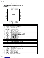
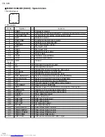
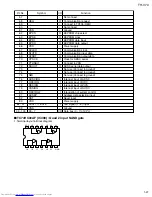
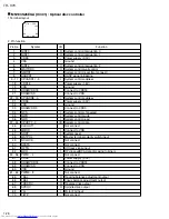
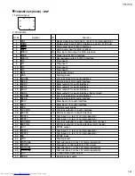
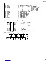
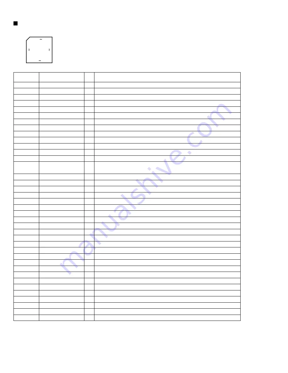
1.Terminal layout
MN101C49GKD1 (IC801) : System micon
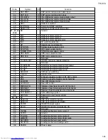
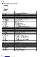
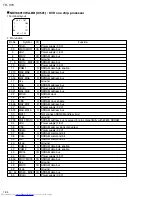
Pin No.
Symbol
Function
2. Pin function
I/O
1
25
75
51
100 76
26 50
VREF-
NTSEL(RGB--SEL)
VER/HOR SEL
SW1
PHOTOSW
LOCK
VERSION
KEY1
KEY2
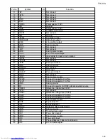
VREF+
VDD
OSC2
OSC1
GND
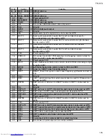
XI
XO
DI-DO
D.O.MUTE
DI-CK
RXD (DATA OUT)
TXD (DATA IN)
SCLK
CS
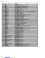
CPU-RESET
INTP
REMOCON
RDS ST
SAFETY1
RESET
DSP RST
DSP RDY
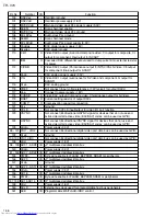
AVC-OUT
AVC-IN
VIDEO-MUTE1
VIDEO-MUTE2
VIDEO-Y/C-MIX
VIDEO-RGB
DSP-COM
-
I
I
I
I
I
I
I
I
-
-
O
I
-
O
I
O
O
O
O
I
I
O
O
I
I
I
I
I
O
O
O
I
O
O
O
O
O
Connect to ground
NTSC/PAL discrimination(RGB/YC switching discrimination) signal
Vertical/Horizontal setting discrimination signal
Slide door switch1
Loading mechanism photo switch
Slide door lock detection(AD)
Area discrimination signal
Key input1 (AD)
Key input2 (AD)
Reference power supply
Power supply
Oscillator output (8MHz)
Oscillator input (8MHz)
Ground
Not used (Connect to ground)
Not used (Not connect)
PANECON serial communication data output
MP3/JPEG mode: H (for DVD disc)
PANECON serial communication clock
Serial communication data output for PANTERA
Serial communication data input for PANTERA
Serial communication clock for PANTERA
Transmit request for PANTERA communication
Reset signal for PANTERA
Receive request for PANTERA communication (Interruption)
Remote control signal input (interruption)
RDS communication strobe (interruption)
Short detecting signal 1
Syscon reset input
DSP micom reset input
DSP micom ready
AV compulink output
AV compulink input
Video driver mute 1 control
Video driver mute 2 control
Video driver YCMIX control
Video driver RGB control
DSP serial communication data output
Summary of Contents for TH-V70
Page 55: ...TH V70 1 55 M E M O ...