


TH-V70
1-11
Fig.1
Fig.2
Fig.3
LED board
Top chassis
Claw
a
Short land sections
b
CN101
DVD servo board
Flexible wire
CN202
CN201
Top chassis
DVD mechanism assembly
Projection
e
Projection
d
Claw
c
B
B
A
DVD mechanism assembly
A
Protector
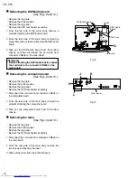
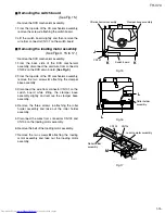
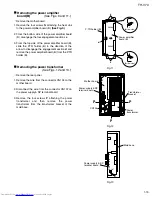
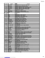
<DVD mechanism assembly section>
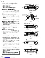
Removing the LED board
(See Fig. 1.)
From the top side of the DVD mechanism
assembly, disengage the claw
a
of the top chassis
attaching the LED board and then remove the LED
board.
[Caution] Be sure to solder the short land
sections b on the flexible wire before
disconnecting the flexible wire from
connector CN101 on the DVD servo
board.
If the flexible wire is disconnected
without attaching solder, the pickup
unit may be destroyed by static
electricity.
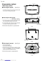
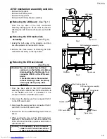
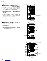
Remove the top plate.
Remove the bottom panel.
Remove the top panel.
Remove the DVD mechanism assembly.
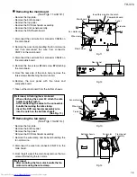
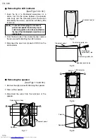
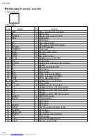
Removing the DVD mechanism
assembly
(See Fig. 2.)
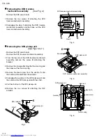
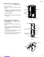
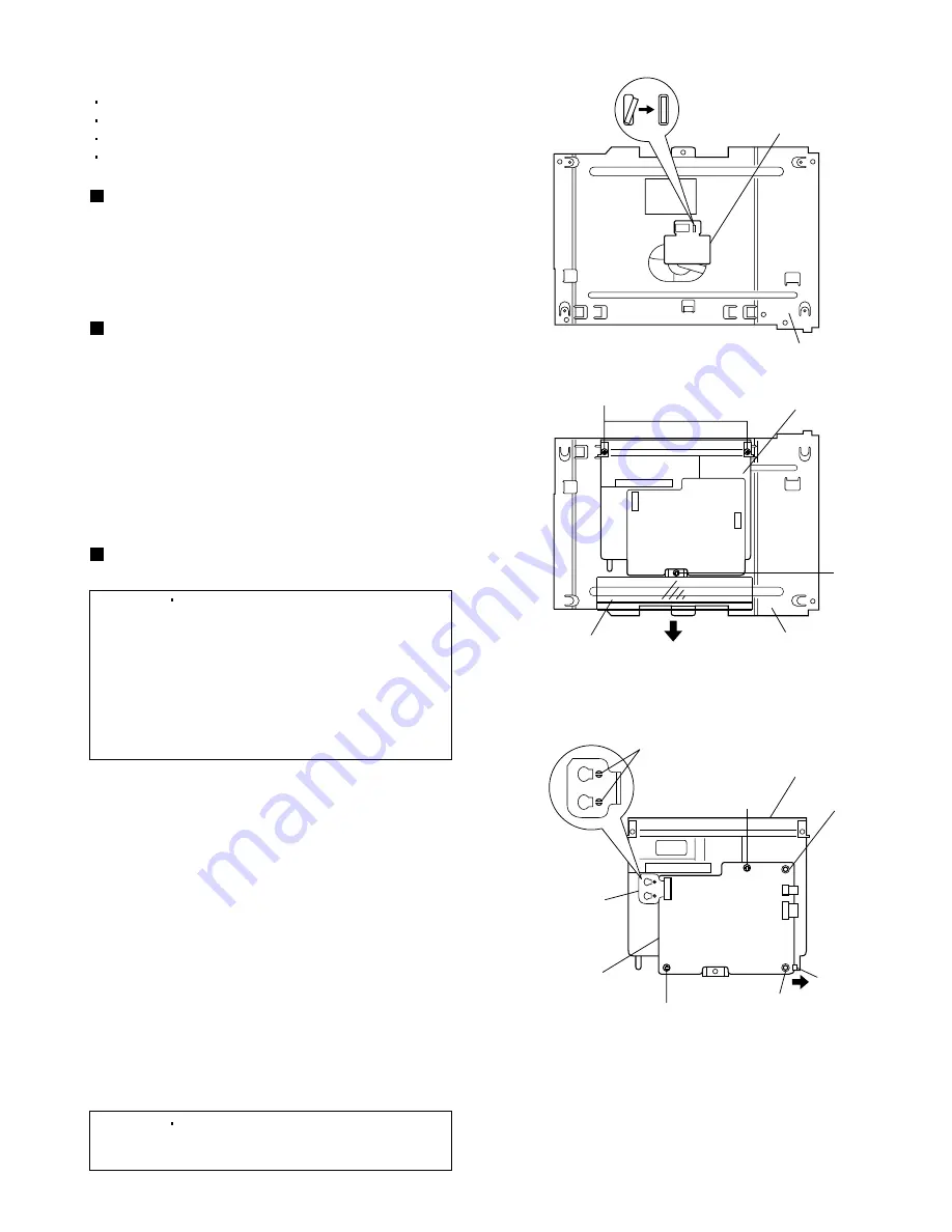
Removing the DVD servo board
(See Fig. 3.)
[Caution] In the assembly, be sure to remove
solder from the short land sections
b after connecting the flexible wire.
1.
2.
3.
4.
5.
From the back side of the DVD mechanism
assembly, attach solder to the short land sections
b
of the flexible wire that is connected to the
connector CN101 of the DVD servo board.
Disconnect the flexible wire from connector CN101
on the DVD servo board.
Disconnect the card wires from connectors CN201
and CN202 on the DVD servo board.
Remove the two screws
B
attaching the DVD servo
board.
While pushing the claw
c
of the DVD mechanism
assembly in the direction of the arrow, remove the
DVD servo board from the projections
d
and
e
in an
upward direction.
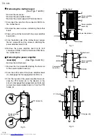
Extend the both sides of the protector, and then
raise the protector in the direction of arrow.
Remove the three screws
A
attaching the DVD
mechanism assembly on the top chassis.
1.
2.
Summary of Contents for TH-V70
Page 55: ...TH V70 1 55 M E M O ...


