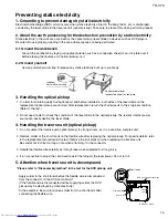


TH-V70
1-17
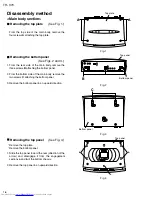
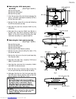
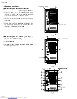
Fig.4
Heat sink
Fig.5
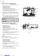
Fig.6
Power transformer
Volume bracket
Mother board
Pre-amplifier
board
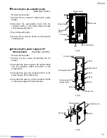
Pre-amplifier board
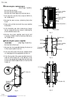
Pre-amplifier board
CN101
Nut
Power supply & SP
terminal board
Volume bracket
CN201
CN101
Volume bracket
F
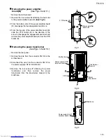
H
H
G
G
CN211
Mother board
Power cord
CN210
CN108
CN111
CN110
CN107
Push button
AC bracket
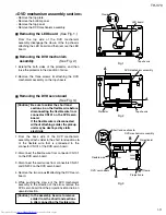
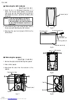
Removing the pre-amplifier board
(See Figs. 4 to 6.)
1.
2.
3.
4.
Remove the two screws
F
attaching the volume
bracket.
Disconnect the pre-amplifier board from the
connector CN201 on the mother board and take
out the pre-amplifier board.
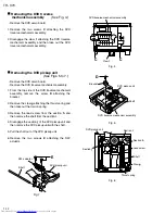
Pull out the push button.
Remove the two screws
G
and nut attaching the
volume bracket.
Remove the rear panel.
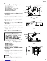
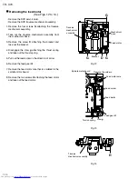
Removing the power supply & SP
terminal board
(See Figs. 4 and 5.)
1.
2.
3.
4.
Remove the two screws
H
attaching the AC
bracket.
Disconnect the power supply & SP terminal board
from the connectors CN210 and CN211 on the
mother board.
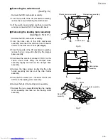
Disconnect the wire from connector CN107 on the
power supply & SP terminal board.
Disconnect the power cord from connector CN108
on the power supply & SP terminal board.
Remove the rear panel.
Summary of Contents for TH-V70
Page 55: ...TH V70 1 55 M E M O ...


