


TH-V70
1-18
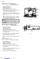
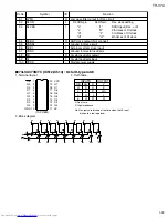
Fig.7
Fig.8
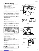
Fig.9
Fig.10
Power transformer
CN104
Mother board
Mold base
Power amplifier
board (A)
Power amplifier
board (A)
P.TR holder (A)
P.TR holder (A)
P.TR holder (B)
Power amplifier
board (B)
Power amplifier
board (B)
J
J
N
M
J
J
J
K
M
N
L
K
L
M
N
CN202
CN206
CN203
CN103
CN102
Mother board
Power amplifier
board (A)
CN205
a
a
b
(Bottom side)
1
2
(Bottom side)
1
2
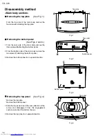
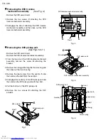
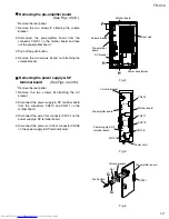
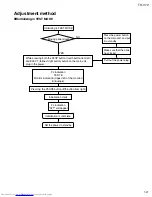
Removing the mother board
(See Figs. 7 and 8.)
1.
2.
3.
4.
5.
Disconnect the wire from the connector CN104 on
the mother board.
Remove the seven screws
J
attaching the mother
board.
Take out the mother board with the power amplifier
board (A,B).
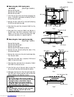
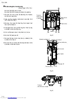
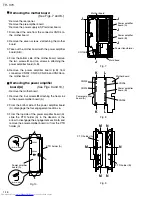
From the bottom side of the mother board, remove
the two screws
K
and two screws
L
attaching the
power amplifier board (A,B).
Remove the power amplifier board (A,B) from
connectors CN202, CN203, CN205 and CN206 on
the mother board.
Remove the rear panel.
Remove the pre-amplifier board.
Remove the power supply & SP terminal board.
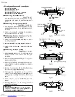
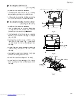
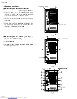
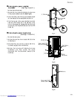
Removing the power amplifier
board (A)
(See Figs. 9 and 10.)
1.
2.
3.
Remove the four screws
M
attaching the heat sink
to the power amplifier board (A).
From the bottom side of the power amplifier board
(A), disengage the four engagement sections
a
.
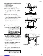
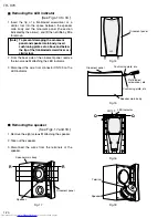
From the top side of the power amplifier board (A),
slide the P.TR holder (A) in the direction of the
arrow to disengage the engagement section
b
and
remove the power amplifier board (A) from the P.TR
holder (A).
Remove the mother board.
Summary of Contents for TH-V70
Page 55: ...TH V70 1 55 M E M O ...


