background image

12

English

Å

Ï

Ó

ı

Ç

Î

Ì

Ô

DVR

OUT(REC)

DVR/DVD
IN(PLAY)

DVR

OUT(REC)

DVR/DVD

IN(PLAY)

FRONT

COMPONENT VIDEO

MONITOR

OUT

DVR/DVD

IN

VCR(DBS)

IN

DVD

MULTI IN

CENTER

SUBWOOFER

SURR-L

SURR-R

È

Y

P

B

P

R

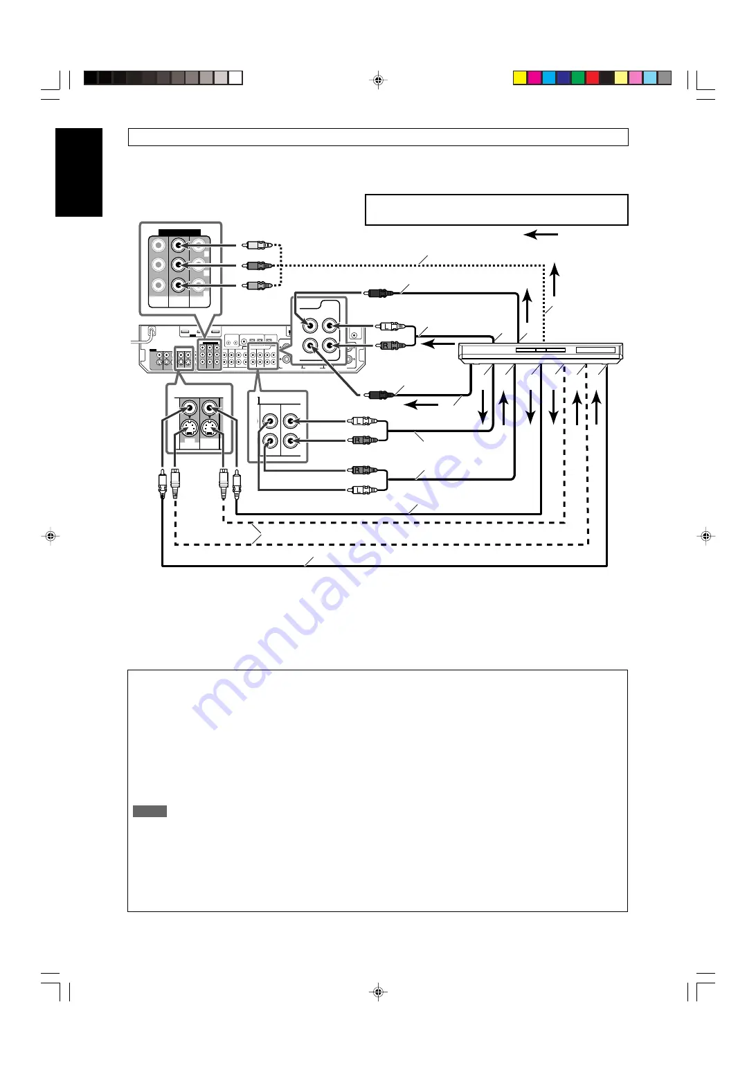
When you connect a DVD recorder or DVD player with its analog discrete output jacks (DVD MULTI IN):

If your DVD recorder or DVD player has analog 5.1 channel output jacks, use the connection below. When a DVD Audio disc is played
back, the original high-quality sounds can be reproduced by using this connection.

Do not connect the AC power plug to the wall outlet until all connections are completed.

Å

To left/right surround channel audio output

ı

To center channel audio output

Ç

To component video output
• Connect Y, P

B

, and P

R

 correctly.

Î

To subwoofer output

To left/right front channel audio output

Ï

Only for DVD recorder: 

To left/right front channel

audio input

Ì

To composite video output

Ó

To S-video output

È

Only for DVD recorder: 

To S-video input

Ô

Only for DVD recorder: 

To composite video input

Stereo audio cable
(not supplied)

Monaural audio cable
(not supplied)

Monaural audio cable
(not supplied)

Component video cable (not supplied)

Composite video cable
(not supplied)

S-video cable (not supplied)

Stereo audio cable
(not supplied)

DVD recorder or
DVD player

Composite video cable (not supplied)

White

Red

White

Red

Green

Blue

Red

: signal current

Turn off all components before making connections.

• When you connect other components, refer also to their manuals.

When you enjoy sound recorded in DVD-Audio...

You can enjoy sound recorded in DVD-Audio both with analog
or digital methods.

With analog method:

• connect your DVD recorder or DVD player to this receiver

according to the diagram above.

• select “A MULTI” in the audio input setting. (See page 20.)

With digital method:

• connect your DVD recorder or DVD player and TV to this

receiver with the HDMI cables. (See page 11.)

• select “HDMI” in the audio input setting. (See page 20.)

NOTES

• When selecting “A MULTI” in the audio input setting or when

multi channel PCM signals (see page 42) are coming in with
selecting “HDMI” in the audio input setting, you can listen to
the front channel sounds (left and right) only by using the
headphones. 3D HEADPHONE mode (see page 43) is not
available.

• When selecting “A MULTI” in the audio input setting or when

multi channel PCM signals (see page 42) are coming in with
selecting “HDMI” in the audio input setting, the following items
are not available:

– DECODE MODE (see page 21)
– CC Converter (see page 22)
– EX/ES/PLllx (see page 30)
– DUAL MONO (see page 30)
– SUBWFR OUT (see page 30)
– CROSSOVER (see page 31)
– LFE ATT (see page 31)
– MIDNIGHT (see page 31)
– AUDIO DELAY (see page 31)
– DIGITAL EQ 63Hz/250Hz/1kHz/4kHz/16kHz (see page 37)
– BASS BOOST (see page 37)
– INPUT ATT (see page 37)
– Sound parameters for Surround/DSP modes (see pages 37

and 38)

– Surround/DSP modes (see pages 41 to 45)

• When you enjoy sound recorded in DVD-Audio through the

HDMI connection, use a DVD recorder or DVD player
compatible with HDMI version 1.1.

Red

White

09-15RX-D702B[C]_f.p65

05.9.14, 1:41 PM

12

Summary of Contents for RXD702B - AV Receiver

Page 1: ...English Français LVT1437 008A C INSTRUCTIONS MANUEL D INSTRUCTIONS RX D702B AUDIO VIDEO CONTROL RECEIVER RECEPTURE DE COMMANDE AUDIO VIDEO cover_RX D702B C p65 05 9 14 1 40 PM 3 ...

Page 2: ...ot cause harmful interference 2 This device must accept any interference received including interference that may cause undesired operation Responsible Party JVC Americas Corp Address 1700 Valley Road Wayne New Jersey 07470 Telephone Number 973 317 5000 For Canada pour le Canada This Class B digital apparatus complies with Canadian ICES 003 Cet appareil numérique de la classe B est conforme à la n...

Page 3: ...enjoy 7 1 channel surround by playing 2 channel or multi channel software K2 Technology K2 technology has been designed to enable natural audio reproduction achieving a drastic reduction in digital distortion and creating original sound ambience with high precision CC Compression Compensative Converter CC Converter eliminates jitter and ripples achieving a drastic reduction in digital distortion b...

Page 4: ...al input DIGITAL IN terminals DIGITAL IN 1 2 3 31 Setting the Audio delay level AUDIO DELAY 31 Memorizing the volume level for each source ONE TOUCH OP 32 Selecting the source for HDMI terminal and COMPONENT VIDEO jacks HDMI SELECT CMPNT SELECT 32 Selecting the output video signals VIDEO OUTPUT 32 Superimposing the menus SUPERIMPOSE 32 Sound adjustments 33 Basic adjustment items 33 Operation throu...

Page 5: ...MODE button 21 e SURROUND button 45 r Adjusting buttons for Digital Equalizer 37 D EQ FREQ D EQ LEVEL t CC CONVERTER button 22 y Adjusting buttons for Surround DSP modes parameters C center TONE EFFECT 37 38 u Adjusting buttons for speaker and subwoofer output levels 36 FRONT L FRONT R CENTER SUBWFR SURR L SURR R S BACK L S BACK R i VOLUME button 20 o DVR DVD mode selector 49 52 MUTING button 21 a...

Page 6: ...S jack 20 w USB terminal 17 e AUX input jacks 15 Digital optical terminal S video jack VIDEO jack AUDIO jacks r Display window 5 t Remote sensor 6 See pages in parentheses for details AUDIO VIDEO CONTROL RECEIVER STANDBY ON CC CONVERTER SETTING ADJUST SURROUND DVR DVD VCR DBS TV USB FM AM SOURCE SELECTOR MULTI JOG MASTER VOLUME SET TUNER PRESET AUX HDMI PUSH OPEN 4 5 6 q 7 8 9 p 3 2 1 e w r t PHON...

Page 7: ...0 21 41 42 LINEAR PCM 96 24 Signal and speaker indicators 22 NEO 6 indicator 42 VIRTUAL SB surround back indicator 44 3D PHONIC indicator 42 43 DSP indicator 43 and indicator 41 43 Main display B bass BOOST indicator 37 MIDNIGHT indicator 31 _ Frequency unit indicators MHz for FM stations kHz for AM stations 1 ANALOG indicator 20 2 DIGITAL and DIGITAL AUTO indicator 20 21 3 DUAL MONO indicator 30 ...

Page 8: ...ure around the receiver must be between 5 C and 35 C Make sure there is good ventilation around the receiver Poor ventilation could cause overheating and damage the receiver Leave sufficient distance between the receiver and the TV Handling the receiver Do not insert any metal object into the receiver Do not disassemble the receiver or remove screws covers or cabinet Do not expose the receiver to ...

Page 9: ...on is poor connect an outdoor single vinyl covered wire not supplied to the AM EXT terminal Keep the AM loop antenna connected FM antenna connection Connect the FM antenna supplied to the FM 75 Ω COAXIAL terminal as a temporary measure Extend the supplied FM antenna horizontally If the reception is poor connect an outdoor FM antenna not supplied Before attaching a 75 Ω coaxial cable with a connect...

Page 10: ...g one surround back speaker set S BACK OUT to S BACK OUT 1SPK see page 29 and connect the surround back speaker to the left surround back speaker terminal No sound comes from the speaker if you connect it to the right surround back speaker terminal Connecting the powered subwoofer By connecting a subwoofer you can enhance the bass or reproduce the original LFE signals recorded in digital software ...

Page 11: ...COMPONENT VIDEO jacks MONITOR OUT and a playing video component is connected to the receiver through the HDMI terminal VCR DBS IN or DVR DVD IN you cannot view the playback picture on the TV NOTES When playing back audio and video with the HDMI connection the HDMI lamp on the front panel lights up Set the audio input setting to HDMI when you enjoy sound with the HDMI connection See Selecting the a...

Page 12: ...ct the AC power plug to the wall outlet until all connections are completed signal current DO NOT use a TV through a VCR or a TV with a built in VCR otherwise the picture may be distorted S video cable not supplied Stereo audio cable not supplied Composite video cable not supplied Red White NOTES If connecting a TV only with the HDMI cable and setting the video input setting see page 20 to HDMI th...

Page 13: ... a digital audio cable coaxial or optical When shipped from the factory the digital coaxial terminal DIGITAL IN 1 DVR DVD on the rear of the receiver is set for a DVD recorder and DVD player For details of digital audio connection see page 16 If your DVD recorder or DVD player is equipped with the analog multi channel output terminals you can enjoy the sound recorded in DVD Audio by connecting you...

Page 14: ... you connect other components refer also to their manuals When you enjoy sound recorded in DVD Audio You can enjoy sound recorded in DVD Audio both with analog or digital methods With analog method connect your DVD recorder or DVD player to this receiver according to the diagram above select A MULTI in the audio input setting See page 20 With digital method connect your DVD recorder or DVD player ...

Page 15: ...well using a digital audio cable coaxial or optical When shipped from the factory the digital optical terminal DIGITAL IN 3 VCR on the rear of the receiver is set for a VCR For details of digital audio connection see page 16 When connecting a VCR with a HDMI cable or component video cable set HDMI SELECT or CMPNT SELECT to VCR see page 32 signal current Available video input setting for each video...

Page 16: ... HDMI cable you can enjoy digital sound as well using a digital audio cable coaxial or optical When shipped from the factory the digital optical terminal DIGITAL IN 2 DBS on the rear of the receiver is set for a DBS tuner For details of digital audio connection see page 16 When connecting a DBS tuner with a HDMI cable or component video cable set HDMI SELECT or CMPNT SELECT to DBS see page 32 DBS ...

Page 17: ...ails Stereo audio cable not supplied Composite video cable not supplied S video cable not supplied Digital optical cable not supplied Video camera etc signal current Available video input setting for each video output setting Available Not available HDMI CMPNT S C HDMI CMPNT S C VIDEO INPUT VIDEO OUTPUT Select the appropriate VIDEO INPUT see page 20 according to the connection you have made If you...

Page 18: ...l optical cable unplug the protective plug NOTES The digital signal format transmitted through the DIGITAL OUT terminal is the same as that of the input signal For example when the DTS signals are coming the DTS signals are transmitted The digital audio signals coming through the following terminals cannot be transmitted through the DIGITAL OUT terminal USB WIRELESS ANTENNA terminal USB terminal H...

Page 19: ... 4 Turn on the receiver then slide the USB WIRELESS switch on the rear to ID LEARNING and select the source as USB WIRELESS When you slide the switch the lamp in the switch starts flashing 5 Set the volume to minimum IMPORTANT Always set volume to 0 when connecting or disconnecting the other equipment 6 Press and hold ID on the transmitter to make a wireless communication with the receiver When yo...

Page 20: ... and you can check whether the drivers are installed If no sound comes from the speakers check the following items For both USB WIRELESS and USB TERMINAL check the USB device is recognized properly check the playback software in your PC is compatible with the USB device open the Control Panel on your PC select Sounds and Audio Devices Audio tab Sound playback Default device and check Default devic...

Page 21: ...ach time you press USB the mode alternates between USB WIRELESS and USB TERMINAL Source lamps 1 Turn on the power Press STANDBY ON or AUDIO on the remote control The standby lamp goes off and the source lamp of the current source lights in red Current source name appears To turn off the power into standby Press STANDBY ON or AUDIO on the remote control again The standby lamp lights in red NOTES A ...

Page 22: ...remote control ONLY Press VIDEO INPUT to select the video input setting Each time you press the button the input setting changes as follows This setting is memorized for each source NOTES For VCR and DBS you can select HDMI and CMPNT for the source you assigned in HDMI SELECT and CMPNT SELECT see page 32 When the video input setting and the audio input setting are both set to HDMI changing the vid...

Page 23: ... the display for a while Lights up when Dolby Digital signal comes in Flashes when DOLBY DIGITAL is selected for any software other than Dolby Digital Lights up when conventional DTS signal comes in Flashes when DTS is selected for any software other than DTS 96 24 Lights up when DTS 96 24 signal comes in NOTE When DGTL AUTO cannot recognize the incoming signal no digital signal format indicator l...

Page 24: ...n the corresponding speaker is set to SMALL or LARGE and also when required for the current playback LINEAR PCM L LS SB RS S WFR PL NEO 6 DSP 3D PHONIC LFE C 96 24 AUTO SURR VIRTUAL SB HEADPHONE x DIGITAL DIGITALAUTO ANALOG DUAL MONO SB S SB R L LS SB RS S WFR LFE C SB S SB R L LS SB RS S WFR LFE C SB S SB R Turning off the power with the Sleep Timer You can fall asleep while listening to music Sl...

Page 25: ...er distance and output level you have set before will be inactive You can see the setting process on the TV screen and the display during Smart Surround Setup If you have turned off the display cancel the Dimmer see page 21 otherwise you cannot see the information on the display Smart Surround Setup will not be done correctly if you or other object blocks the sound When you change your speakers do...

Page 26: ...t the sound three times The receiver exits from Smart Surround Setup To cancel Smart Surround Setup press EXIT while SETTING UP flashes No other operations can be accepted after SETTING UP stops flashing Complete the Smart Surround Setup To check the current setting made by Smart Surround Setup press SMART S SETUP while the receiver is in normal operation mode The setting values appear On the disp...

Page 27: ...o sound channel 30 DUAL MONO SUBWFR OUT Select sounds emitted from the subwoofer 30 SUBWOOFER OUT CROSSOVER Select the cutoff frequency to the subwoofer 31 CROSSOVER LFE ATT Attenuate the bass LFE sounds 31 LFE ATT MIDNIGHT Reproduce a powerful sound at night 31 MIDNIGHT MODE DIGITAL IN 1 Select the component connected to the digital DIGITAL IN 1 coaxial terminal 1 DVR DVD 31 DIGITAL IN 2 Select t...

Page 28: ...R 100Hz LFE ATT 0dB MIDNIGHT OFF ENTER EXIT DUAL MONO SUBWOOFER OUT LFE ATT MIDNIGHT MODE DIGITAL IN 1 DIGITAL IN 2 DIGITAL IN 3 ONE TOUCH OPERATION HDMI SELECT COMPONENT SELECT VIDEO OUTPUT AUDIO DELAY SUPERIMPOSE See page 28 See page 28 See page 28 See page 28 See page 28 See page 29 See page 29 See page 29 See page 29 See page 29 See page 29 See page 29 See page 29 See page 29 See page 30 See p...

Page 29: ...U 5 To change the screen simply pressing 5 or repeatedly You can go to the next previous screen On the front panel turn MULTI JOG The submenu previously selected appears Operations On the TV screen On the display Usable buttons and their functions Usable buttons and their functions Button indications on the screen The buttons for operating the menu are shown on the TV screen You can operate the me...

Page 30: ... and DSP modes register the setting about the speaker after all connections are completed 7 Setting subwoofer information SUBWOOFER Select whether you have connected a subwoofer or not SUBWOOFER YES Select when you have connected a subwoofer The subwoofer indicator S WFR lights up on the display You can adjust the subwoofer output level see page 36 SUBWOOFER NO Select when you have disconnected a ...

Page 31: ...t to NO you cannot select S BACK OUT When S BACK OUT is set to S BACK OUT 1SPK connect the surround back speaker to the left surround back speaker terminal see page 8 No sound comes from the surround back speaker if you connect it to the right surround back speaker terminal 7 Setting the speaker distance The distance from your listening point to the speakers is one of the important elements to obt...

Page 32: ... the LFE signals Dolby Digital multi channel software DTS multi channel software When playing analog source or linear PCM software no LFE signals are emitted Activating the EX ES PLIIx setting EX ES PLIIx Depending on this setting available Surround modes for digital multi channel software vary EX ES PLIIx reproduction or 5 1 channel reproduction Select an appropriate setting for your enjoyment Fo...

Page 33: ... this receiver automatically reallocates the bass sound elements assigned to the small speaker to the large speakers To use this function properly set this crossover frequency level according to the size of the small speaker connected If you have selected LARGE for all speakers see page 28 this function will not take effect CROSS OFF appears CROSSOVER 80Hz Select when the cone speaker unit built i...

Page 34: ...r memorizes some settings separately for each source In addition you can store the volume level for each source with the other memorized settings See page 22 This receiver memorizes the volume level when you turn off the power and when you change the source ONE TOUCH OP ON Select to store the volume level separately for each source The ONE TOUCH OPERATION indicator lights up on the display ONE TOU...

Page 35: ...CT ROOM SIZE Select the room size for your virtual listening ROOM SIZE room 37 LIVENESS Select the liveness level for your virtual LIVENESS listening room 38 PANORAMA Add wraparound sound effect with side PANORAMA wall image 38 CENTER WIDTH Adjust the center channel localization CENTER WIDTH between the center speaker and the left right speakers 38 Items To do DIMENSION Adjust sound localization p...

Page 36: ...CENTER WIDTH PANORAMA CENTER GAIN CENTER TONE DIMENSION CNTR ALIGNMENT See page 37 See page 37 See page 37 See page 37 See page 37 See page 37 See page 37 See page 37 See page 37 See page 38 See page 38 See page 38 See page 38 See page 38 See page 38 See page 38 See page 36 See page 36 See page 36 See page 36 See page 36 See page 36 See page 36 See page 36 Press SET Setup menu configuration Items ...

Page 37: ...s 2 or 3 repeatedly then press SET The on screen display returns to the previous ADJUST MENU In this example ADJUST MENU 1 appears on the TV screen and SUBWFR LVL appears on the display On the front panel turn MULTI JOG then press SET 5 Repeat steps 2 to 4 to set other items if necessary The submenu previously selected appears On the TV screen On the display The setting item previously selected ap...

Page 38: ... output levels SUBWOOFER LEVEL subwoofer output level FRONT L LEVEL left front speaker output level FRONT R LEVEL right front speaker output level CENTER LEVEL center speaker output level SURR L LEVEL left surround speaker output level SURR R LEVEL right surround speaker output level S BACK L LEVEL left surround back speaker output level S BACK R LEVEL right surround back speaker output level You ...

Page 39: ...em directly from the remote control Adjustable range 1 to 5 in 1 step intervals Initial setting ROOM SIZE 3 As the number increases the interval between reflections increases so that you will feel as if you were in a larger room Normally select 3 Adjusting the equalization patterns DIGITAL EQ 63Hz 250Hz 1kHz 4kHz 16kHz You can adjust equalization patterns in five frequency bands center frequency 6...

Page 40: ...e an adjustment it is memorized for each DSP mode You cannot adjust this item directly from the remote control Adjustable range 1 to 5 in 1 step intervals Initial setting LIVENESS 3 As the number increases the attenuation level of reflections over time decreases so that acoustics change from Dead to Live Normally select 3 7 Adjusting the panorama control for Pro Logic IIx Music and Pro Logic II Mu...

Page 41: ...e you start remember There is a time limit in doing the following steps If the setting is canceled before you finish start from step 2 again From the remote control ONLY 1 Tune in to the station you want to preset see Tuning in to stations manually above If you want to store the FM reception mode for this station select the FM reception mode you want See Selecting the FM reception mode on page 40 ...

Page 42: ...selected band is tuned in 2 Press TUNER PRESET P appears on the display and MULTI JOG now works for selecting preset channels 3 Turn MULTI JOG to select a preset channel number To increase the preset channel numbers turn MULTI JOG clockwise To decrease the preset channel numbers turn MULTI JOG counterclockwise Selecting the FM reception mode When an FM stereo broadcast is hard to receive or noisy ...

Page 43: ...olby Digital EX DOLBY D EX is a digital surround encoding format that adds the third surround channels called surround back Compared to the conventional Dolby Digital 5 1CH these newly added surround back channels can reproduce more detailed movements behind you while viewing the video software In addition surround sound localization will become more stable Dolby Surround Dolby Pro Logic II Dolby ...

Page 44: ... channel that developed from Dolby Pro Logic II The matrix based conversion method used for Dolby Pro Logic IIx makes no limitation for the cutoff frequency of the surround treble This receiver provides three types of Dolby Pro Logic IIx modes Pro Logic IIx Movie PLIIx MOVIE Pro Logic IIx Music PLIIx MUSIC and Pro Logic IIx Game PLIIx GAME When Dolby Pro Logic IIx is activated PLIIx MOVIE PLIIx MU...

Page 45: ...back 2 channel analog or digital source the built in Dolby Pro Logic II decoder is activated and the indicator lights up Early reflections Direct sounds Reflections from behind When using the DAP mode the sounds come out of all the connected and activated speakers If SURROUND SPK is set to NO in the speaker setting see page 28 JVC s original 3D PHONIC processing which has been developed to create ...

Page 46: ...ant to apply the processing set the EX ES PLIIx setting to OFF see page 30 2 When S BACK OUT is set to SB OUT 1SPK D PLIIx MOVIE is changed to DOLBY D EX and DTS PLIIx MOVIE is changed to DTS EX 3 When S BACK SPK is set to NO Virtual Surround Back is activated for the modes and the VIRTUAL SB indicator lights up on the display 4 When S BACK SPK is set to NO PLllx MOVIE PLllx MUSIC and PLllx GAME a...

Page 47: ... incoming signals For details see page 44 Activating one of the Surround DSP modes automatically recalls the memorized settings and adjustments To adjust the speaker output level see page 36 When activating one of the Surround DSP modes you can adjust CENTER TONE see page 38 When activating one of the Surround DSP modes except PLIIx MUSIC PLII MUSIC NEO 6 MUSIC and ALL CH STEREO you can adjust CNT...

Page 48: ... type of video terminals can output only through the terminal of the same type So you need to connect the video components to this receiver using one of the following three ways When using the AV COMPU LINK remote control system set the video output and video input setting for the DVD player and the VCR correctly see Selecting the video input setting on page 20 and Selecting the output video signa...

Page 49: ...cting procedure 1 If you have already plugged your VCR DVD player TV and this receiver into the AC outlets unplug their AC power cords first 2 Connect your VCR DVD player TV and this receiver as follows using the cables with the monaural mini plugs not supplied See Connections 1 on the previous page 3 Connect the audio input output jacks on the VCR DVD player TV and this receiver using the audio c...

Page 50: ... You can always perform the following operation VCR Turn on or off the VCR After pressing VCR you can perform the following operations on the VCR CHANNEL Change the channel numbers on the VCR 1 9 0 Select the channel numbers on the VCR 3 Start playback 7 Stop playback 8 Pause playback To release it press 3 FF Fast wind a tape REW Rewind a tape 3 Start recording 8 Enter recording pause To start rec...

Page 51: ... number menu item etc If these buttons do not function normally use the remote control supplied with your DVD recorder or DVD player Refer also to the manuals supplied with the DVD recorder or DVD player for details 1 2 3 4 5 6 7 8 9 10 0 10 After setting the mode selector correctly you can perform the following operations on the DVD recorder or DVD player See the instructions supplied with the DV...

Page 52: ...DEO After pressing TV you can perform the following operations on the TV CHANNEL Change the channel numbers 1 9 0 100 10 Select the channel numbers See the instructions supplied with the TV for details 5 Try to operate your TV by pressing TV When your TV turns on or off you have entered the correct code If more than one code is listed for your brand of TV try each one until the correct one is ente...

Page 53: ...with the VCR for details 5 Try to operate your VCR by pressing VCR When your VCR turns on or off you have entered the correct code If more than one code is listed for your brand of VCR try each one until the correct one is entered Manufacturers codes for VCR Manufacturers codes are subject to change without notice If they are changed this remote control cannot operate the equipment Manufacturer Co...

Page 54: ...rrect one is entered Manufacturer Codes JVC 01 Hitachi 02 Kenwood 03 04 Magnavox 05 Marantz 06 Mitsubishi 07 Onkyo 08 09 Panasonic 10 Philips 06 Pioneer 11 Proscan 12 RCA 12 Samsung 13 Sony 14 Toshiba 05 Yamaha 15 Zenith 05 16 Initial setting 01 Manufacturers codes are subject to change without notice If they are changed this remote control cannot operate the equipment Changing the transmittable s...

Page 55: ...ach source correctly The video input setting is set to HDMI A video or audio format not compatible with this receiver and or TV is played A HDCP compatible TV is not connected The receiver failed to recognize HDMI connected components A HDMI cable longer than 5 m 15 ft is used SOLUTION Plug the power cord into an AC outlet 1 Stop the playback source 2 Turn on the receiver again then turn the volum...

Page 56: ...al is too weak The station is too far away The wrong antenna is being used Antennas are not connected properly Ignition noise from automobiles SOLUTION Set the mode selector correctly then press the corresponding source selecting button before operation Remove the obstruction Replace batteries Set the mode selector to the proper position Connect an outdoor FM antenna or contact your dealer Select ...

Page 57: ...kHz 1 dB Bass Boost 4 dB 1 dB at 100 Hz Equalization at DSP operation Center frequency 63 Hz 250 Hz 1 kHz 4 kHz 16 kHz Control range 8 dB Specifications Video Video Input Sensitivity Impedance Composite video DVR DVD VCR DBS 1 V p p 75 Ω S video DVR DVD VCR DBS Y luminance 1 V p p 75 Ω C chrominance burst 0 286 V p p 75 Ω Component DVR DVD VCR DBS Y luminance 1 V p p 75 Ω PB PR 0 7 V p p 75 Ω Vide...

Page 58: ...2 canaux ou multicanaux Technologie K2 La technologie K2 a été conçue pour permettre une reproduction naturelle du son atteignant une réduction radicale de la distorsion numérique et en créant un son d ambiance original de haute précision Convertisseur CC Compression Compensatrice Le convertisseur CC élimine les instabilités et les ondulations atteignant une réduction radicale de la distorsion num...

Page 59: ...es prises d entrée numériques DIGITAL IN DIGITAL IN 1 2 3 31 Réglage du niveau de retard audio AUDIO DELAY 31 Mémorisation du niveau de volume pour chaque source ONE TOUCH OP 32 Sélection de la source pour la prise HDMI et les prises COMPONENT VIDEO HDMI SELECT CMPNT SELECT 32 Sélection des signaux vidéo de sortie VIDEO OUTPUT 32 Superposition des menus SUPERIMPOSE 32 Ajustements sonores 33 Élémen...

Page 60: ...37 D EQ FREQ D EQ LEVEL t Touche CC CONVERTER 22 y Touches d ajustement pour les paramètres des modes Surround DSP C TONE tonalité centrale EFFECT 37 38 u Touches de réglage pour le niveau de sortie des enceintes et du caisson de grave 36 FRONT L FRONT R CENTER SUBWFR SURR L SURR R S BACK L S BACK R i Touche VOLUME 20 o Sélecteur de mode DVR DVD 49 52 Touche MUTING 21 a Touche DVD MENU 49 52 s Tou...

Page 61: ...ERTER SETTING ADJUST SURROUND DVR DVD VCR DBS TV USB FM AM SOURCE SELECTOR MULTI JOG MASTER VOLUME SET TUNER PRESET AUX HDMI PUSH OPEN 4 5 6 q 7 8 9 p 3 2 1 e w r t PHONES USB DIGITAL S VIDEO VIDEO L AUDIO R AUX Comment ouvrir la porte avant Derrière la porte avant Poussez sur PUSH OPEN 1 Touche STANDBY ON et témoin d attente 19 2 Touche CC CONVERTER 22 3 Touche SETTING 25 27 4 Touche ADJUST 33 35...

Page 62: ... BOOST TUNED STEREO SLEEP AUTO MUTING INPUT ATT HEADPHONE MHz kHz x MIDNIGHT DIGITAL DIGITALAUTO ANALOG DUAL MONO SB S SB RDS TA NEWS INFO ONE TOUCH OPERATION CC CONVERTER 1 2 AUTO MODE 1 2 3 5 8 7 4 6 0 9 _ Indicateurs de format du signal numerique 20 21 41 42 LINEAR PCM 96 24 Indicateurs de signal et d enceinte 22 Indicateur NEO 6 42 Indicateur VIRTUAL SB Surround arrière 44 Indicateur 3D PHONIC...

Page 63: ... être comprise entre 5 C et 35 C Assurez vous qu il y a une bonne ventilation autour de l appareil Une mauvaise ventilation peut entraîner une surchauffe et endommager l ampli tuner Laissez suffisamment d espace entre l ampli tuner et le téléviseur Manipulation de l ampli tuner N insérez aucun objet métallique à l intérieur de l ampli tuner Ne démontez pas l ampli tuner ni ne retirez les vis les c...

Page 64: ...H Tournez l antenne cadre jusqu à ce que vous obteniez la meilleure réception possible Si la réception est mauvaise connectez un fil extérieur recouvert de vinyle non fournie à la prise AM EXT Laissez l antenne cadre AM connectée Connexion de l antenne FM Connectez provisoirement l antenne FM fournie à la prise FM 75 Ω COAXIAL Étendez l antenne FM fournie horizontalement Si la réception est mauvai...

Page 65: ...ne seule enceinte Surround arrière réglez S BACK OUT sur S BACK OUT 1SPK voir page 29 connectez l enceinte Surround arrière à la prise de l enceinte Surround arrière gauche Aucun son ne sort de l enceinte si vous la connectez à la prise de l enceinte Surround arrière droite Connexion du caisson de grave actif En connectant un caisson de grave vous pouvez améliorer les graves et reproduire les sign...

Page 66: ... appareil vidéo est connecté à l ampli tuner par la prise HDMI VCR DBS IN ou DVR DVD IN vous ne pouvez pas voir l image de lecture sur le téléviseur REMARQUES Lors de la lecture d un signal audio et vidéo avec la connexion HDMI le témoin HDMI sur le panneau avant s allume Régler l entrée audio sur HDMI si vous souhaitez écouter le son avec une connexion HDMI Référez vous à Sélection du réglage de ...

Page 67: ...e ni un téléviseur avec magnétoscope intégré sinon l image risque d être déformée Câble S vidéo non fourni Câble audio stéréo non fourni Câble vidéo composite non fourni Rouge Blanc REMARQUES Si vous connectez un téléviseur uniquement avec un câble HDMI et réglez le réglage d entrée vidéo voir page 20 sur HDMI l affichage sur l écran n apparaît pas sur l écran du téléviseur Pour utiliser l afficha...

Page 68: ...ue coaxial ou optique À l expédition de l usine la prise coaxiale numérique DIGITAL IN 1 DVR DVD à l arrière de l ampli tuner est réglée pour un enregistreur de DVD et un lecteur de DVD Pour en savoir plus sur la connexion audio numérique référez vous à la page 16 Si votre enregistreur de DVD ou lecteur de DVD est muni de prises de sortie multicanaux analogiques vous pouvez profiter d un son enreg...

Page 69: ... enregistré en DVD Audio avec la méthode analogique ou numérique Avec la méthode analogique Connectez votre enregistreur de DVD ou lecteur de DVD à cet ampli tuner en fonction de l illustration ci dessus Choisissez A MULTI dans le réglage de l entrée audio Voir page 20 Avec la méthode numérique Connectez votre enregistreur de DVD ou lecteur de DVD et le téléviseur à l ampli tuner avec les câble HD...

Page 70: ...e coaxial ou optique À l expédition de l usine la prise optique numérique DIGITAL IN 3 VCR à l arrière de l ampli tuner est réglée pour un magnétoscope Pour en savoir plus sur la connexion audio numérique référez vous à la page 16 Lors de la connexion d un magnétoscope avec un câble HDMI ou un câble vidéo en composantes réglez HDMI SELECT ou CMPNT SELECT sur VCR voir page 32 flux du signal Réglage...

Page 71: ...ussi du son numérique en utilisant un câble audio numérique coaxial ou optique À l expédition de l usine la prise optique numérique DIGITAL IN 2 DBS à l arrière de l ampli tuner est réglée pour un tuner DBS Pour en savoir plus sur la connexion audio numérique référez vous à la page 16 Lors de la connexion d un tuner DBS avec un câble HDMI ou un câble vidéo en composantes réglez HDMI SELECT ou CMPN...

Page 72: ...onnexion Voir page 20 pour les détails Câble audio stéréo non fourni Câble vidéo composite non fourni Câble S vidéo non fourni Câble optique numérique non fourni Caméra vidéo etc flux du signal Réglage d entrée vidéo disponible pour chaque réglage de sortie vidéo Disponible Indisponible HDMI CMPNT S C HDMI CMPNT S C VIDEO INPUT VIDEO OUTPUT Choisissez le réglage approprié pour VIDEO INPUT voir pag...

Page 73: ... signal numérique transmis par la prise DIGITAL OUT est le même que celui du signal d entrée Par exemple si des signaux DTS sont entrés les mêmes signaux DTS sont sortis Les signaux audio numériques entrant par les prises suivantes ne peuvent pas être transmis par la prise DIGITAL OUT Prise USB WIRELESS ANTENNA Prise USB Prise HDMI VCR DBS IN et prise HDMI DVR DVD IN Connexion du cordon d alimenta...

Page 74: ... POWER PLAYER ID USB WIRELESS TRANSMITTER SUITE À LA PAGE SUIVANTE ANTENNA USB WIRELESS LEARNING ID ON Antenne USB sans fil fournie Émetteur USB sans fil fourni Ordinateur Ordinateur Câble USB non fourni 4 Mettez l ampli tuner sous tension puis faites glisser le commutateur USB WIRELESS à l arrière sur la position ID LEARNING puis choisissez USB WIRELESS comme source Quand vous faites glisser le c...

Page 75: ...l Bus controllers La fenêtre suivante apparaît et il est possible de vérifier si les pilotes ont été installés Si aucun son ne sort des enceintes vérifiez les points suivants Pour la méthode USB WIRELESS et USB TERMINAL vérifiez si le périphérique USB est reconnu correctement vérifiez si le logiciel de lecture de votre ordinateur est compatible avec le périphérique USB ouvrez le panneau de configu...

Page 76: ... mode alterne entre USB WIRELESS et USB TERMINAL Témoins de source 1 Mise de l appareil sous tension Appuyez sur STANDBY ON ou sur AUDIO sur la télécommande Le témoin d attente s éteint et le témoin source de la source actuelle s allume en rouge Le nom de la source actuelle apparaît Pour mettre l appareil hors tension en attente Appuyez de nouveau sur STANDBY ON ou sur AUDIO sur la télécommande Le...

Page 77: ...ce réglage quand vous connectez un enregistreur de DVD ou un lecteur de DVD aux prises DVD MULTI IN voir page 12 L indicateur ANALOG s allume sur l affichage Quand TV est choisi comme source seul DIGITAL ou ANALOG apparaît sur l affichage comme réglage d entrée audio VIDEO INPUT AUDIO INPUT REMARQUES HDMI est disponible uniquement pour la source avec HDMI choisi comme réglage d entrée vidéo voir l...

Page 78: ... AUTO et l indicateur DIGITAL AUTO s allume sur l affichage Si les symptômes suivants se produisent pendant la lecture d un logiciel Dolby Digital ou DTS alors que DGTL AUTO est choisi suivez la procédure ci dessous Aucun son ne sort au début de la lecture Il y a du bruit lors de la recherche ou du saut de chapitres ou de plages A partir de la télécommande SEULEMENT Appuyez sur DECODE MODE pour ch...

Page 79: ...LARGE et aussi quand elles sont nécessaires pour la lecture actuelle LINEAR PCM L LS SB RS S WFR PL NEO 6 DSP 3D PHONIC LFE C 96 24 AUTO SURR VIRTUAL SB HEADPHONE x DIGITAL DIGITALAUTO ANALOG DUAL MONO SB S SB R L LS SB RS S WFR LFE C SB S SB R L LS SB RS S WFR LFE C SB S SB R L S WFR R AUTO SURR SLEEP ANALOG 10min 20min 30min 40min 50min 60min 90min OFF annulé 80min 70min Mise hors tension de l a...

Page 80: ...ge Surround Intelligent les réglages suivants sont calculés automatiquement en une seule action un claquement de main La distance des enceintes par rapport à celle de l enceinte la plus proche Le niveau de sortie des enceintes sauf pour le caisson de grave REMARQUES Le réglage intelligent du Surround peut ne pas fonctionner correctement avec certaines enceintes ou certaines enceintes peuvent cause...

Page 81: ...age a été réalisé partiellement La distance des enceintes desquelles le sont a été détecté est réglée sur 9 0m 30ft L ampli tuner quitte le Réglage Surround Intelligent Si MANUAL apparaît C est que l ampli tuner n a pas réussi à détecter le son trois fois L ampli tuner quitte la Réglage Surround Intelligent Pour annuler le réglage intelligent du Surround appuyez sur EXIT pendant que SETTING UP cli...

Page 82: ...inte centrale 28 CENTER SPK SURR SPK Enregistrer la taille des enceintes surround SURROUND SPK 28 S BACK SPK Enregistrer la taille des enceintes surround S BACK SPK arrière 28 S BACK OUT Enregistrez votre nombre d enceintes S BACK OUT Surround arrière 29 DISTANCE UNIT Choisir l unité de mesure pour la distance des DIST UNIT enceintes 29 FL SPK DIST Enregistre la distance de l enceinte avant FRONT ...

Page 83: ...MONO SUBWOOFER OUT LFE ATT MIDNIGHT MODE DIGITAL IN 1 DIGITAL IN 2 DIGITAL IN 3 ONE TOUCH OPERATION HDMI SELECT COMPONENT SELECT VIDEO OUTPUT AUDIO DELAY SUPERIMPOSE Voir page 28 Voir page 28 Voir page 28 Voir page 28 Voir page 28 Voir page 29 Voir page 29 Voir page 29 Voir page 29 Voir page 29 Voir page 29 Voir page 29 Voir page 29 Voir page 29 Voir page 30 Voir page 30 Voir page 30 Voir page 31 ...

Page 84: ...TING MENU 5 Pour changer l écran appuyez simplement répétitivement sur 5 ou Vous pouvez aller à l écran suivant précédent Sur le panneau avant tournez la molette MULTI JOG Le dernier sous menu choisi apparaît Opérations Sur l écran du téléviseur Sur l affichage Touches utilisables et leurs fonctions Touches utilisables et leurs fonctions Indications des touches sur l écran Les touches permettant d...

Page 85: ...SPK enceintes surround arrière Enregistrez la taille des enceintes connectées LARGE Choisissez ce réglage quand la taille du cône du haut parleur est supérieure à 12 cm SMALL Choisissez ce réglage quand la taille du cône du haut parleur est inférieure à 12 cm NO Choisissez ce réglage si vous n avez pas connecté d enceinte Ne peut pas être choisi pour les enceintes avant Réglage initial LARGE pour ...

Page 86: ... SURR SPK est réglé sur NO le réglage de l enceinte Surround arrière est fixé sur NO Quand S BACK SPK est réglé sur NO vous ne pouvez pas choisir S BACK OUT Quand S BACK OUT est réglé sur S BACK OUT 1SPK connectez l enceinte Surround arrière à la prise d enceinte Surround arrière gauche voir page 8 Aucun son ne sort de l enceinte Surround arrière si vous la connectez à la prise de l enceinte Surro...

Page 87: ...t lors de la lecture des supports suivants avec signaux LFE Supports multicanaux Dolby Digital Supports multicanaux DTS Lors de la lecture d une source analogique ou d un support PCM linéaire aucun signal LFE n est émis Réglage DUAL MONO Ch 1 Ch 2 Ch 1 Ch 2 Ch 1 Ch 1 ALL Ch 1 Ch 2 Ch 1 Ch 2 Ch 1 Ch 2 Ch 1 Ch 2 Ch1 Ch 2 Ch 2 Ch 2 L R L R C L R MAIN SUB Sans Surround Avec le mode Surround en service...

Page 88: ...lisez des petites enceintes dans n importe position cet appareil redirige automatiquement les éléments graves affectés aux petites enceintes vers les grandes enceintes Pour utiliser cette fonction correctement régler le niveau de la fréquence de transition en fonction de la taille des petites enceintes connectées Si vous avez choisi LARGE pour toutes les enceintes voir page 28 cette fonction n a a...

Page 89: ...li tuner mémorise certains réglages séparément pour chaque source De plus vous pouvez mémoriser le niveau de volume pour chaque source avec les autres réglages mémorisés voir page 22 Cet ampli tuner mémorise le niveau de volume quand vous mettez l ampli tuner hors tension quand vous changez de source ONE TOUCH OP ON Choisissez ce réglage pour mémoriser le niveau de volume séparément pour chaque so...

Page 90: ...s éléments qui ne sont pas disponibles pour le réglage actuel Le nom du réglage donné ci dessous est l indication de l affichage sur l écran et le nom entre parenthèse est l indiction de l affichage Éléments Pour SUBWOOFER LEVEL 1 Ajuster le niveau de sortie du caisson SUBWFR LVL de grave 36 FRONT L LEVEL 1 2 Ajuster le niveau de sortie de l enceinte FRONT L LVL avant gauche 36 FRONT R LEVEL 1 2 A...

Page 91: ...MENSION CNTR ALIGNMENT Voir page 37 Voir page 37 Voir page 37 Voir page 37 Voir page 37 Voir page 37 Voir page 37 Voir page 37 Voir page 37 Voir page 38 Voir page 38 Voir page 38 Voir page 38 Voir page 38 Voir page 38 Voir page 38 Voir page 36 Voir page 36 Voir page 36 Voir page 36 Voir page 36 Voir page 36 Voir page 36 Voir page 36 Appuyez sur SET Configuration du menu de réglage Les réglages sur...

Page 92: ...ppuyez sur SET L affichage sur l écran retourne au menu ADJUST MENU précédent Dans cet exemple ADJUST MENU 1 apparaît sur l écran du téléviseur et SUBWFR LVL apparaît sur l affichage Sur le panneau avant tournez la molette MULTI JOG puis appuyez sur SET 5 Répétez les étapes 2 à 4 pour régler si nécessaire d autres éléments Le dernier sous menu choisi apparaît Sur l écran du téléviseur Sur l affich...

Page 93: ...age les indications sont légèrement différentes de celle qui apparaissent sur l affichage sur l écran C est à cause du nombre limite de caractères pouvant être affichés sur l affichage Ex SUBWOOFER LEVEL 10 apparaît à la place de SUBWFR 10 sur l affichage BASS BOOST OFF apparaît à la place de B BOOST OFF sur l affichage Ajustement des niveaux de sortie des enceintes SUBWOOFER LEVEL niveau de sorti...

Page 94: ...Si cela se produit vous devez atténuer le niveau du signal d entrée pour éviter la déformation du son Une fois que vous avez réalisé un ajustement il est mémorisé pour chaque source Vous ne pouvez pas ajuster ce réglage directement à partir de la télécommande INPUT ATT ON Choisissez ce réglage pour atténuer le niveau du signal de sortie L indicateur INPUT ATT s allume sur l affichage INPUT ATT NOR...

Page 95: ...morisé pour chaque mode DSP Vous ne pouvez pas ajuster ce réglage directement à partir de la télécommande Plage d ajustement 1 à 5 par intervalle d un pas Réglage initial LIVENESS 3 Plus le nombre est grand plus le niveau d atténuation des réflexions dans le temps diminue de façon que l acoustique change de plat à direct Normalement choisissez 3 7 Ajustement de la commande panoramique pour Pro Log...

Page 96: ...mémoriser les stations préréglées Avant de commencer rappelez vous Il y a un temps limite pour réaliser les étapes suivantes Si le réglage est annulé avant la fin recommencez à partir de l étape 2 A partir de la télécommande SEULEMENT 1 Accordez la station que vous souhaitez prérégler voir Accord manuel des stations ci dessus Si vous souhaitez mémoriser le mode de réception FM pour cette station c...

Page 97: ...e la dernière bande choisie est accordée 2 Appuyez sur TUNER PRESET P apparaît sur l affichage et MULTI JOG peut être utilisé pour choisir les canaux préréglés 3 Tournez la molette MULTI JOG pour choisir un numéro de canal Pour augmenter le numéro du canal préréglé tournez la molette MULTI JOG dans le sens des aiguilles d une montre Pour diminuer le numéro du canal préréglé tournez la molette MULT...

Page 98: ...s qu avec le Dolby Pro Logic Dolby Digital EX Dolby Digital EX DOLBY D EX est un format de codage Surround numérique qui ajoute des troisièmes canaux Surround appelés Surround arrière Comparé au Dolby Digital conventionnel à 5 1 canaux les nouveaux canaux surround arrière permettent de reproduire des mouvements arrières plus détaillés lors de la visualisation d un support vidéo En plus la localisa...

Page 99: ...u 6 1 canaux La méthode de conversion matricielle utilisée pour le Dolby Pro Logic IIx n a pas de limites pour la fréquence de coupure ni pour les aigus du Surround Cet ampli tuner offre trois types de modes Dolby Pro Logic IIx Pro Logic IIx Movie PLIIx MOVIE Pro Logic IIx Music PLIIx MUSIC et Pro Logic IIx Game PLIIx GAME Quand le Dolby Pro Logic IIx est mise en service PLIIx MOVIE PLIIx MUSIC ou...

Page 100: ...pendant la lecture d une source analogique ou numérique à 2 canaux le décodeur intégré Dolby Pro Logic II est mis en service et l indicateur s allume Réflexions premières Sons directs Réflexions arrière Lors de l utilisation du mode DAP les sons sortent de toutes les enceintes connectées et en service Si SURROUND SPK est réglé sur NO dans les réglages d enceinte voir page 28 le traitement original...

Page 101: ...er réglez EX ES PLIIx sur OFF voir page 30 2 Quand S BACK OUT est réglé sur SB OUT 1SPK D PLIIx MOVIE change sur DOLBY D EX et DTS PLIIx MOVIE change sur DTS EX 3 Quand S BACK SPK est réglé sur NO le Surround arriére virtuel est mis en service pour les modes et l indicateur VIRTUAL SB s allume sur l affichage 4 Quand S BACK SPK est réglé sur NO PLllx MOVIE PLllx MUSIC et PLllx GAME sont changés re...

Page 102: ...antes Si le réglage est annulé avant la fin recommencez à partir de l étape 2 1 Choisissez et reproduisez n importe quelle source Les modes Surround DSP ne sont pas disponibles quand A MULTI est choisi pour le réglage de l entrée audio voir page 20 ou quand des signaux PCM multicanaux voir page 42 enregistrés en DVD Audio sont entrés Assurez vous d avoir choisi le mode d entrée analogique ou numér...

Page 103: ...par un type de prise vidéo peuvent être sortis uniquement par le même type de prise vidéo C est pourquoi vous devez connecter les appareils vidéo à cet ampli tuner en utilisant une des trois méthodes suivantes Lors de l utilisation du système de commande à distance AV COMPU LINK réglez la sortie vidéo et l entrée vidéo pour le lecteur de DVD et le magnétoscope correctement voir Sélection du réglag...

Page 104: ... de connexion 1 Si vous avez déjà branché votre magnétoscope lecteur de DVD téléviseur et cet ampli tuner sur des prises secteur débranchez d abord leur cordon d alimentation secteur 2 Connectez votre magnétoscope lecteur de DVD téléviseur et cet ampli tuner en utilisant des cordons à fiches mini monaurales non fourni Référez vous à Connexions 1 à la page précédente 3 Connectez les prises d entrée...

Page 105: ...s réaliser l opération suivante VCR Mettre sous ou hors tension le magnétoscope Après avoir appuyé sur VCR vous pouvez réaliser les opérations suivantes sur le magnétoscope CHANNEL Changer le numéro de canal sur le magnétoscope 1 9 0 Choisir le numéro de canal sur le magnétoscope 3 Démarrer la lecture 7 Arrêter la lecture 8 Arrêter momentanément la lecture pause Pour la reprendre appuyez sur 3 FF ...

Page 106: ... touches ne fonctionnent pas normalement utilisez la télécommande fournie avec votre enregistreur de DVD ou lecteur de DVD Référez vous aussi aux manuels fournis avec l enregistreur de DVD ou le lecteur de DVD pour plus de détails 1 2 3 4 5 6 7 8 9 10 0 10 Après avoir réglé le sélecteur de mode vous pouvez réaliser les opérations suivantes sur l enregistreur de DVD ou le lecteur de DVD Référez vou...

Page 107: ...O Changer le mode d entrée TV ou VIDEO Après avoir appuyé sur TV vous pouvez réaliser les opérations suivantes sur le téléviseur CHANNEL Changer le numéro de canal 1 9 0 100 10 Choisir le numéro de canal Référez vous aux instructions fournies avec le téléviseur pour les détails 5 Essayez de commander le téléviseur en appuyant sur TV Si votre téléviseur se met sous ou hors tension c est que vous av...

Page 108: ...ez sur cette touche puis sur 3 Référez vous aux instructions fournies avec le magnétoscopes pour les détails 5 Essayez de commander le magnétoscope en appuyant sur VCR Si votre magnétoscope se met sous ou hors tension c est que vous avez entré le code correct S il y a plus d un code dans la liste pour votre fabricant de magnétoscope essayez tous les codes jusqu à ce que vous trouviez le bon Codes ...

Page 109: ...C 01 Hitachi 02 Kenwood 03 04 Magnavox 05 Marantz 06 Mitsubishi 07 Onkyo 08 09 Panasonic 10 Philips 06 Pioneer 11 Proscan 12 RCA 12 Samsung 13 Sony 14 Toshiba 05 Yamaha 15 Zenith 05 16 Réglage initial 01 Les codes de fabricant sont sujets à changement sans notification S ils sont changés cette télécommande ne peut plus commander l appareil Changement des signaux émettables pour la commande d un le...

Page 110: ...déo est réglé sur HDMI Un format vidéo ou audio non compatible avec cet ampli tuner et ou le téléviseur est reproduit Un téléviseur compatible HDCP n est pas connecté L ampli tuner n a pas pu reconnaître les appareils HDMI connectés Un câble HDMI plus long que 5 m 15 pieds est utilisé SOLUTION Branchez le sur une prise secteur murale 1 Arrêter la source de lecture 2 Mettez l appareil de nouveau so...

Page 111: ...est trop faible La station est trop loin Une antenne incorrecte est utilisée Les antennes sont mal connectées Bruit de démarrage d automobiles SOLUTION Réglez le sélecteur de mode correctement puis appuyez sur la touche de sélection de source correspondante avant l opération Retirez l obstacle Remplacez les piles Réglez le sélecteur de mode sur la position correcte Connectez une antenne FM extérie...

Page 112: ...z 1 dB Accentuation des graves 4 dB 1 dB à 100 Hz Égalisation pendant l utilisation du mode DSP Fréquence centrale 63 Hz 250 Hz 1 kHz 4 kHz 16 kHz Plage de commande 8 dB Spécifications Vidéo Sensibilité d entrée vidéo Impédance Vidéo composite DVR DVD VCR DBS 1 V c c 75 Ω S vidéo DVR DVD VCR DBS Y luminance 1 V c c 75 Ω C chrominance en salve 0 286 V c c 75 Ω Composantes DVR DVD VCR DBS Y luminanc...

Page 113: ...0905RYMMDWJEIN EN FR 2005 Victor Company of Japan Limited cover_RX D702B C p65 05 9 14 1 40 PM 2 ...

Page 114: ...Instructions AUDIO VIDEO CONTROL RECEIVER RX D702B BB_RX D702B C p65 05 9 14 1 49 PM 1 ...

Reviews: