ENGLISH
- 11 -
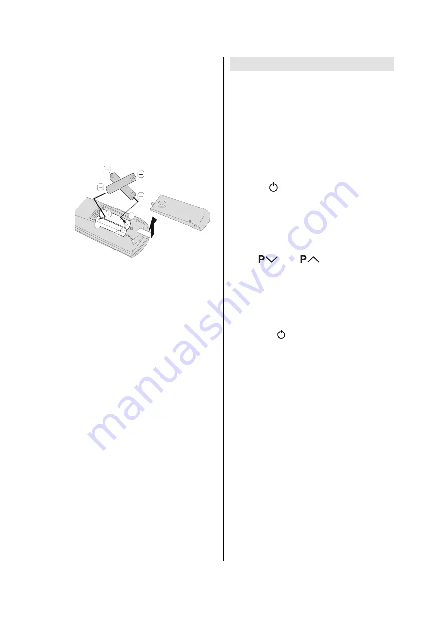
Inserting batteries in the remote
control handset
Remove the battery cover located on the back
of the handset by gently pulling downwards
from the indicated part.
Insert two AA/R6 dry cell or equivalent type of
batteries inside.
Replace the battery cover.
NOTE:
Remove the batteries from remote con-
trol handset when it is not to be used for a long
period.Otherwise it can be damaged due to
any leakage of battery.
Old batteries must be disposed in a desig-
nated area. If performance of the remote con-
trol reduces, replace the batteries with the cor-
rect type. Do not combine a used, old battery
or a new one or mixed battery types. Remove
dead batteries immediately to prevent acid
from leaking into the battery compartment.
Switching the TV ON/OFF
To switch the TV on
Your TV will switch on in two steps:
1-
Connect the
power cord
to the system.
Press the On/Off switch at the rear of the
TV.
Then the TV switches itself to stand-by
mode and the power lamp becomes red
located on the front of the TV.
2-
To switch on the TV from stand-by mode
either:
Press the /
I
button on the remote control
or on the right side of the TV
or,
Press a digit button on the remote control so
that a programme number is selected,
or,
Press
or
buttons on the re-
mote control or on the right side of the TV, so
that last switched off programme is selected.
Either way the TV will switch on and the power
lamp will become green.
To switch the TV off
Press the /
I
button on the remote con-
trol or on the right side of the TV, so the TV
will switch to stand-by mode and the power
lamp will become red.
NOTE:
To switch the TV off completely, press
the On/Off switch at the rear of the TV or re-
move the mains plug from the socket.
Summary of Contents for LT-26B60BU
Page 60: ... No YA352 3 13 PACKING 5 6 7 7 8 7 9 3 2 ...
Page 72: ... No YA352 2 17 2 18 No YA352 MAIN PWB ASS Y 8 8 VE 20224628 MAIN PWB CIRCUIT DIAGRAM 8 8 ...
Page 75: ... No YA352 2 23 2 24 No YA352 TOP PATTERN DIAGRAMS MAIN PWB PATTERN SOLDER SIDE ...
Page 76: ... No YA352 2 25 2 26 No YA352 TOP MAIN PWB PATTERN PARTS SIDE ...
Page 77: ... No YA352 2 27 2 28 No YA352 TOP POWER PWB PATTERN SOLDER SIDE ...
Page 78: ... No YA352 2 29 2 30 No YA352 TOP POWER PWB PATTERN PARTS SIDE ...


