background image

ENGLISH

   - 15 -

3LFWXUH

&RRO
2II

5(6(7

0RGH
&RQWUDVW

%ULJKW
6KDUSQHVV

&RORXU
&RORXU7HPS

1RLVH5HG

%ULJKW

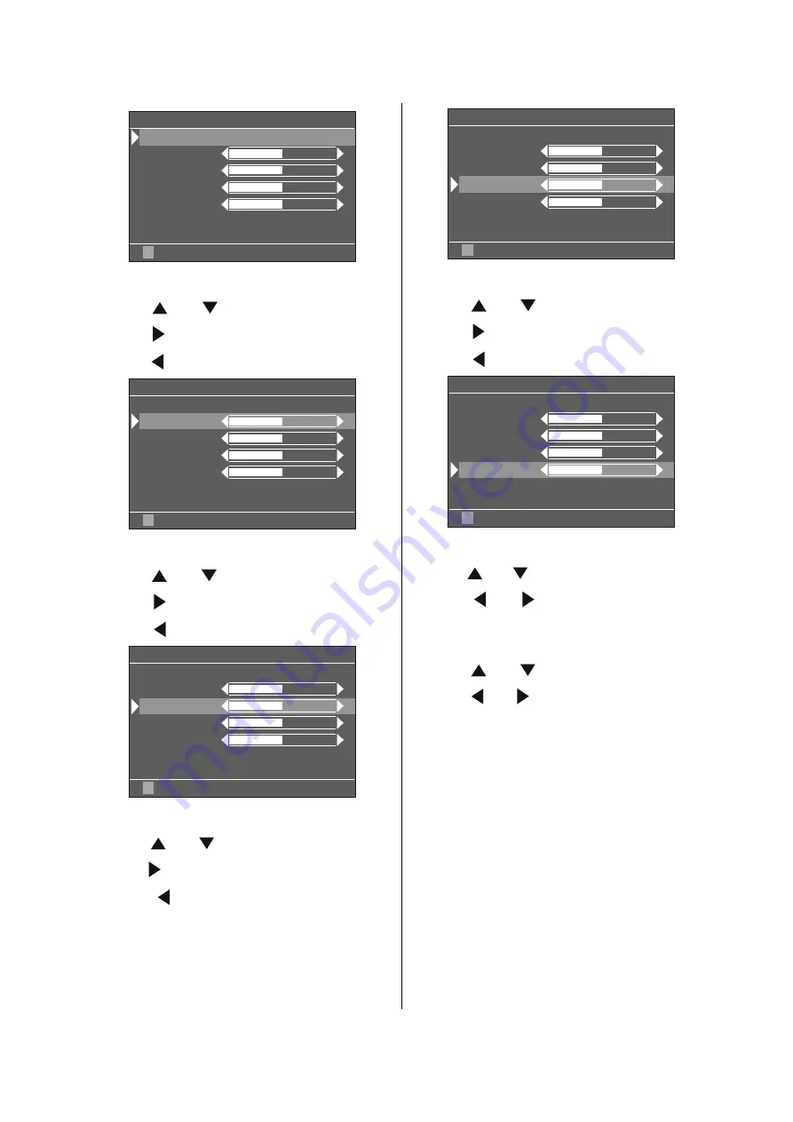
Setting  Contrast

• Using “ ” or “ ” button select 

Contrast

.

• Press “ ” button to increase contrast level.
• Press “ ” button to decrease contrast level.

3LFWXUH

&RRO
2II

5(6(7

0RGH
&RQWUDVW

%ULJKW
6KDUSQHVV

&RORXU
&RORXU7HPS

1RLVH5HG

%ULJKW

Setting 

Bright

• Using “ ” or “ ” button select


Bright

.

• Press “ ” button to increase brightness.
• Press “ ” button to decrease brightness.

3LFWXUH

&RRO
2II

5(6(7

0RGH
&RQWUDVW

%ULJKW
6KDUSQHVV

&RORXU
&RORXU7HPS

1RLVH5HG

%ULJKW

Setting Sharpness

• Using “ ” or “ ” button select 

Sharpness

.

• Press “ ” button to increase sharpness level.
•  Press  “ ”  button  to  decrease  sharpness

level.

3LFWXUH

&RRO
2II

5(6(7

0RGH
&RQWUDVW

%ULJKW
6KDUSQHVV

&RORXU
&RORXU7HPS

1RLVH5HG

%ULJKW

Setting Colour

• Using “ ” or “ ” button select 

Colour

.

• Press “ ” button to increase colour level.
• Press “ ” button to decrease colour level.

3LFWXUH

&RRO
2II

5(6(7

0RGH
&RQWUDVW

%ULJKW
6KDUSQHVV

&RORXU
&RORXU7HPS

1RLVH5HG

%ULJKW

Setting Colour Temp.

• Using “ ” or “ ” button select 

Colour Temp.

• Press “ ” or “ ” button to select “

Warm

”,

“

Cool

” or “

Normal

”.

Setting Noise Reduction

• Using “ ” or “ ” button select 

Noise Red.

• Press “ ” or “ ” button to select Noise Re-

duction level “

Off

” or “

Minimum

” or “

Medium

”

or “

Maximum

”.

Note 1:

At low signal level, the changings on the Noise Reduction

function are not effective when there is menu on the screen.

If the menu is removed, the effect of this function is seen.

At  normal  broadcasting,  Noise  Reduction  changings  are
effective  at  once.

Note 2:

At moving pictures, while Noise Reduction is at maximum

level, some picture distortions may occur. If Noise Reduc-
tion is set to medium or minimum, the picture will improve.

Summary of Contents for LT-26B60BU

Page 1: ...NEL TELEVISION YA352 2005 11 LT 26B60BJ LT 26B60BU LT 26B60SJ LT 26B60SU TABLE OF CONTENTS 1 PRECAUTION 1 3 2 SPECIFIC SERVICE INSTRUCTIONS 1 7 3 DISASSEMBLY 1 10 4 ADJUSTMENT 1 14 5 TROUBLESHOOTING 1 14 P BACK TOP MENU PC TV RM C1860 1 4 5 6 9 8 7 0 2 3 i ZOOM PICTURE MENU AV DVD VCR TV OK ...

Page 2: ...al 60 0cm H 56 6cm V 34 0cm Display Pixels Horizontal 1366 dots Vertical 768 dots W XGA Audio Power Output 8W 8W 10 THD Speaker 5 1cm 12 7cm 2 Aerial terminal VHF UHF F type connector 75Ω unbalanced coaxial EXT 1 EXT 2 Input Output 21 pin Euro connector SCART socket 2 EXT 3 Input Component Audio Y 1V p p Positive Negative sync provided 75Ω RCA pin jack 1 Pb Pr 0 7V p p 75Ω RCA pin jack 2 500mV rms...

Page 3: ...omponents that indicate evidence of overheating should be replaced Always use the manufacturer s replacement components 6 Isolation Check Safety for Electrical Shock Hazard After re assembling the product always perform an isolation check on the exposed metal parts of the cabinet antenna terminals video audio input and output terminals Control knobs metal cabinet screw heads earphone jack control ...

Page 4: ...aracteristics are identified in the Parts List of Service Manual Electrical components having such features are identified by shading on the schematics and by on the Parts List in the Service Manual The use of a substitute replacement which does not have the same safety characteristics as the recommended replacement part shown in the Parts List of Service Manual may cause shock fire or other hazar...

Page 5: ... and the surrounding walls as well as the floor etc Install the unit on stable flooring or stands Take precautionary measures to prevent the unit from tipping in order to protect against accidents and earthquakes 1 3 3 NOTES ON HANDLING 1 WHEN TAKING UNIT OUT OF A PACKING CASE When taking the unit out of a packing case do not grasp the upper part of the unit If you take the unit out while grasping...

Page 6: ...ring transportation and storage as the LCD panel is very vulnerable to lateral impacts and may break During transportation ensure that the unit is loaded along the traveling direction of the vehicle and avoid stacking them on one another For storage ensure that they are stacked in 2 layers or less even when placed upright 1 4 2 OPTICAL FILTER ON THE FRONT OF THE LCD PANEL 1 Avoid placing the unit ...

Page 7: ... OUT 2 AUDIO R input 500mV rms Nominal High impedance Used R1 Used R2 3 AUDIO L output 500mV rms Nominal Low impedance Used TV OUT Used LINE OUT 4 AUDIO GND Used Used 5 GND B Used Used 6 AUDIO L input 500mV rms Nominal High impedance Used L1 Used L2 7 B input 700mV B W 75Ω Used Used 8 FUNCTION SW SLOW SW Low 0V 3V High 8V 12V High impedance Used Used 9 GND G Used Used 10 SCL T V LINK Not used Used...

Page 8: ...IGHT FAULT In this pixel fault a cell that should not light originally is lighting on and off For checking this pixel fault input ALL BLACK SCREEN and find out the cell that is lighting on and off DARK FAULT In this pixel fault a cell that should light originally is not lighting or lighting with the brightness twice as brighter as originally lighting For checking this pixel fault input 100 of each...

Page 9: ...FORMAITION OK BACK MENU Setting menu Setting items Contents Adjust Group Mode Col Temp Contrast Brightness Colour Sharpness Red Green Blue Aps Volume Option 1 First APS If ON TV starts with APS menu at Start up BG DK I L L FM Prs Avl On Adjusts the FM Prescaler value when Automatic Volume Levelling is On Nicam Prs Avl On Adjusts the Nicam Prescal er value when Automatic Volume Levelling is On Scar...

Page 10: ...MBLY Remove the BACK COVER 1 Remove the 1 screw G 2 Remove the HEADPHONE JACK PWB 3 1 7 REMOVING THE POWER SWITCH PWB Remove the FOOT ASSEMBLY Remove the BACK COVER 1 Remove the 4 screws H 2 Remove the POWER SWITCH PWB 3 1 8 REMOVING THE AV TERMINAL BRACKET Remove the FOOT ASSEMBLY Remove the BACK COVER 1 Remove the 2 screws J 2 Remove the AV TERMINAL BRACKET 3 1 9 REMOVING THE MAIN PWB Remove the...

Page 11: ... B C FOOT ASSEMBLY AV TERMINAL BRACKET AV JACK PWB LCD PANEL UNIT BACK COVER AV JACK BRACKT HEADPHONE PWB POWER CORD BUTTON FUNCTION SIDE CONTROL PWB SPEAKER LED PWB DISPLAY SUPPORT DISPLAY SUPPORT FRONT PANEL POWER PWB MAIN PWB POWER SWITCH PWB ...

Page 12: ...l EXT MODE Setting item Setting position POWER Off TV AV TV Setting item Setting position ZOOM AUTO Setting item Setting position MODE Bright Contrast 33 Step Bright 1 26 Step Sharpness 11 Step Colour 36 Step Bright 2 7 Step Colour Temp Cool Nolse Red Min Setting item Setting position Volume 10 Step Bass 16 Step Treble 15 Step Balance 16 Step Hyper Sound Off Sound Mode Mono Setting item Setting po...

Page 13: ...the tweezers and remove the chip part Transistors diodes variable resistors etc 1 Apply extra solder to each lead 2 As shown in the figure push the part with tweezers and alternately melt the solder at each lead Shift and remove the chip part NOTE After removing the part remove remaining solder from the pattern 2 How to install Chip parts Resistors capacitors etc 1 Apply solder to the pattern as i...

Page 14: ...1 14 No YA352 SECTION 4 ADJUSTMENT This service manual does not describe ADJUSTMENT SECTION 5 TROUBLESHOOTING This service manual does not describe TROUBLESHOOTING ...

Page 15: ... No YA352 AV MULTIMEDIA COMPANY DISPLAY CATEGORY 12 3 chome Moriya cho Kanagawa ku Yokohama city Kanagawa prefecture 221 8528 Japan Victor Company of Japan Limited VPT Printed in Japan ...

Page 16: ...G TÉLÉVISEUR À GRAND ÉCRAN LCD MANUEL D INSTRUCTIONS ITALIANO TV A PIENO SCHERMO LCD ISTRUZIONI LT 26B60BU LT 26B60SU WIDE LCD PANEL TV D GUNCEL IB JVC_LT26B60 BU SU SJ 2625W Grup 1 LT 26B60BU SU GRP1 COVER PAGE 2625W 17MB08P 1860UK LT 26B60BU SU 50074712 cdr 09 Eyl l 2005 Cuma 13 38 08 Color profile Disabled Composite Default screen ...

Page 17: ...id places subject to extremely high temperatures or hu midity or locations where the temperature is likely to fall below 5ºC 41ºF DO ensure that the TV is not standing on the mains lead DO NOT cut off the mains plug from this equipment this incorporates a spe cial Radio Interference Filter the removal of which will impair its performance Hot Moderate Climate Conditions This device is suitable for ...

Page 18: ...leave equipment switched on when it is unattended unless it is specifically stated that it is designed for unattended operation or has a standby mode Switch the equipment off and make sure your family know how to do this Special arrangements may need to be made for infirm or handicapped people DON T continue to operate the equipment if you are in any doubt about it working normally or it is damage...

Page 19: ...inst the TV Doing so may cause the TV to fall over and lead to injuries CAUTION To avoid electric shock or damage to the unit first firmly connect the small end of the power cord to the rear of the TV and then plug the larger end of power cord into an AC outlet CAUTION The TV screen may be damaged if the TV is carried as shown in the diagram The TV should always be carried by two people ...

Page 20: ... business the loss of recorded data whether caused during normal operation or misuse of the product WARNING NEVER LEAVE A STATIONARY IMAGE ON THE SCREEN If stationary images generated by TELETEXT CHANNELIDENTIFICATION LOGOS COM PUTER DISPLAYS VIDEO GAMES ON SCREEN MENUS etc are left on the TV screen for any length of time they could be come permanently ingrained If you use your television to displ...

Page 21: ... PICTURE Mode button YELLOW Sleep Timer button MENU button Cursor Up button OK button Cursor Right button BACK button Volume buttons Teletext VCR DVD Control buttons PC Control Buttons P buttons Cursor Down button Teletext Button Cursor Left button Stereo Bilingual button GREEN Hyper Sound On Off button RED ZOOM Mode button Information Button T V Link in Programme Menu Mute button ...

Page 22: ...s With certain combinations of connectors and leads the back cover may not be easily fitted If the cover is left off this in no way infringes safety requirements 32 5 03 1 5 5 5 9 5 63 5 63 5 67 1 352 5 00 83 2 1 92 80 83 2 1 0 18 79 9 2 3 21 ...

Page 23: ...ENGLISH 7 3 8 2 1 17 11 7 7 3 1387 7 7 8 2 287 7 50 1 3E 3U RPSRQHQW XGLR Q 5 RPSRQHQW XGLR Q 6 9LGHR Q 9LGHR Q XGLR 5 XGLR XGLR 5 XGLR 6XEZRRIHU 2XW 32 5 25 1387 21 2 6 7 9 9 a 32 5 ...

Page 24: ...ENGLISH 8 How to remove the stand Loosen the 5 screws that attach the stand to the TV Gently pull the stand downwards to remove it ...

Page 25: ...l with a sturdy tie using the hook on the back of the TV this will prevent it from falling over Use curtains or blinds to prevent direct sunlight falling on the screen A floor and table top stand are available for this television or and angled bracket which enables the TV to be wall mounted The LCD display panels are manufactured using an extremely high level of precision technol ogy however somet...

Page 26: ...ic 14 9 Zoom 16 9 Zoom 16 9 Zoom Subtitle modes Automatic sound mute when no transmis sion When no valid signal is detected after 5 min utes the TV switches itself automatically to stand by mode NTSC Playback PLL Channel Search TV Picture in PC if PC input available PC input Support Up to 1366 x 768 Audio Lineout BeforeSwitchingonyourTV Power connection IMPORTANT The TV set is designed to oper ate...

Page 27: ...N OFF To switch the TV on Your TV will switch on in two steps 1 Connect the power cord to the system Press the On Off switch at the rear of the TV Then the TV switches itself to stand by mode and the power lamp becomes red located on the front of the TV 2 To switch on the TV from stand by mode either Press the I button on the remote control or on the right side of the TV or Press a digit button on...

Page 28: ...n to exit the menu If you have a T V Link compatible VCR con nected to the EXT 2 terminal press but ton to display T V Link menu Then follow the operating procedure Downloading data to VCR in the following T V Link section T V Link When a T V Link compatible VCR connected to the EXT 2 terminal on the TV it is easier to set up the VCR and to view videos T V Link uses the following features To use T...

Page 29: ... your TV s main power is turned off Set your TV s main power to on StandBy Mode OperatingtheTV You can operate your TV using both the re mote control handset and onset buttons Volume setting and programme selection can be made by using the buttons at the control panel on the right side of the TV Operating with the buttons on the TV Volume Setting Press button to decrease volume or button to increa...

Page 30: ... do not run continuously The fifteenth channel in the list for ex ample may not be channel number 15 but channel number 17 MenuSystem Your TV has been designed with a menu sys tem to provide an easy manipulation of a multi function system The TV is controlled by choos ing the commands which are displayed on the screen MAIN MENU Press the MENU button The main menu will be displayed in the middle of...

Page 31: ...ORXU 7HPS 1RLVH 5HG ULJKW Setting Colour Using or button select Colour Press button to increase colour level Press button to decrease colour level 3LFWXUH RRO 2II 5 6 7 0RGH RQWUDVW ULJKW 6KDUSQHVV RORXU RORXU 7HPS 1RLVH 5HG ULJKW Setting Colour Temp Using or buttonselect ColourTemp Press or button to select Warm Cool or Normal Setting Noise Reduction Using or button select Noise Red Press or butt...

Page 32: ...Level Using or button select Treble Press button to increase treble level Press button to decrease treble level Setting Balance It allows adjusting the distribution between the left and right speakers Using or button select Balance Press button to change balance right ward Press button to change balance leftward Hyper Sound Using or buttonselect Hyper Sound Pressing or button will turn this fea tu...

Page 33: ...the TV goes automatically to stand by mode Child Lock You can use this feature to prevent children turning the TV on off or changing programmes or adjustments etc without remote control Using or button select Child Lock Press button to select Child Lock On or Off When Off is selected there will be no differ ence in the operation of your TV When On is selected the TV can only be controlled by the r...

Page 34: ...s to continue search process To stop the search process when you want press or buttons at any time Decoder EXT 2 You can use this mode to connect any de coder to your TV Press the or buttons to set it On or Off When you select Decoder EXT 2 On EXT 2 output will be chosen as TV mode only and any scrambled channels will be un scrambled through decoder connected your TV via EXT 2 output Setting VCR V...

Page 35: ...tore the channel name To cancel the Name mode press the BLUE button To delete a channel Delete 1 Choose the channel you want to delete 2 Press the YELLOW button to enter the De lete mode 3 Press the YELLOW button to delete it To cancel the Delete mode press the BLUE button To change the programme number of a channel Insert 1 Choose the channel you want to change the programme number 2 Press the GR...

Page 36: ...und Indicator The alternatives of the indicator are Mono Ste reo Dual I and Dual II This indicator is dis played under the programme number indica tor on the screen I II button is used to select Mono or Stereo or Dual I or Dual II 0RQR In Mono broadcast or in forced mono for ste reo broadcast 6WHUHR In Stereo broadcast XDO If dual broadcast detected Dual I is selected in default and also can be se...

Page 37: ...Timer is active the timer stops and if no signal detected again the timer is initialized to 5 minutes and starts 3 seconds later again to count down It is not valid in EXT modes No Signal and Out Of Range Detection PC mode In PC Mode as no menu is displayed in case that there is no PC input to the TV it is dis played an OSD message No input signal detected then the TV will turn to be in PC standby...

Page 38: ...ge the position of the picture in Zoom modes except Full and Regular modes by pressing the or button Note You can only choose REGULAR and FULL in PC mode FULL This uniformly stretches the left and right sides of a normal picture 4 3 aspect ratio to fill the wide TV screen For 16 9 aspect ratio pictures that have been squeezed into a normal picture 4 3 aspect ratio use the FULL mode to restore the ...

Page 39: ...se this item to put the picture into correct place automatically Select Auto position item by using or buttons Press OK button Press MENU buttonor BACK buttontostore the value Warning Auto position adjustment recom mended to be done with the full screen image for the proper adjustment Horizontal Position This item shifts the image horizontally to right hand side or left hand side of the screen Sel...

Page 40: ...3 3LFWXUH RQWUDVW ULJKW RORXU 6KDUSQHVV 5HVHW PIP picture is displayed on the screen with button PIP position is changed by button There are four different PIP positions PIP size is changed by button Two dif ferent PIP sizes are available Programme in the PIP window is increased decreased by digit buttons or AV button All EXT modes except EXT 3 are also available in PIP window PIP window is remove...

Page 41: ...ber using digit buttons The page will be searched and the page number will be displayed on the upper left corner of the screen when the selected page is found Now you can display this tele text page by pressing button To Select Double Height Text Press button for the top half of the infor mation page to be displayed in double height text Press button again for the bottom half of the information pa...

Page 42: ...ion diagrams at the end of this sec tion show you where the different equipment should be connected at the back side of the TV Via the Euroconnector Your TV set has 2 Euroconnector sockets If you want to connect peripherals e g video decoder etc which have Euroconnectors to your TV use SCART input If an external device is connected via the Euroconnector socket the TV is switched to AV mode automat...

Page 43: ...der VCR Connect the Video Recorder to the ANT an tenna input socket of the TV with the aerial cable Connect the Video Recorder to the EXT 1 or EXT 2 terminal with the SCART cable or con nect it to the EXT 4 terminal with the audio and video cables NTSC Playback Connect a NTSC video recorder to a terminal Then press AV button to select the corre sponding AV mode NTSC 3 58 4 43 system is detected au...

Page 44: ...ENGLISH 28 PeripheralEquipmentConnections 17 1 0 25 5 8 2 1 5 9 2 1 1 287 1 2 8 7 DECODER FORSATELLITERECEIVER VIDEO HEADPHONE AUDIO AntennaConnections ...

Page 45: ...0 75 Hz and a horizontal sync frequency range of 30 69 KHz The following table is an illustration of some of the typical video display modes RUL RQWDO 9HUWLFDO RU N 9HU 0 RGH UHTXHQF 5 HVROXWLRQ The native resolution of the TFT LCD Panel is 1366 x 768 Therefore using Mode 15 is advised to get the best PC input display quality ...

Page 46: ... of the peripherals No Image on Display Screen Is the aerial connected properly Are the plugs connected tightly to the aerial socket Is the aerial cable damaged Are suitable plugs used to connect the aerial If you are in doubt consult your dealer No Image means that your TV is not receiving any transmission Have you pressed the cor rect buttons on the remote control Try once more PC Picture If no ...

Page 47: ...dcast outputs Video and Audio L R are available EXT 2Terminal Euroconnector 21 pin SCART 2 back of the cabinet Video Input S VIDEO Y C input Audio L R and RGB inputs are available Video and Audio L R outputs are available T V Link functions are available EXT 3Terminal RCA connectors x 5 back of the cabinet Component video Pr Pb Y inputs and Audio L R inputs are available EXT 4Terminal RCA connecto...

Page 48: ...pacitor MF R Metal Film Resistor MF CAP Metalized Film Capacitor MG R Metal Glazed Resistor MM CAP Metalized Mylar Capacitor MP R Metal Plate Resistor MP CAP Metalized Polystyrol Capacitor OM R Metal Oxide Film Resistor PP CAP Polypropylene Capacitor CMF R Coating Metal Film Resistor PS CAP Polystyrol Capacitor UNF R Non Flammable Resistor TF CAP Thin Film Capacitor CH V R Chip Variable Resistor M...

Page 49: ...20211052 3 12 AV JACK P W BOARD ASS Y VE 20230006 3 12 LED P W BOARD ASS Y VE 20211058 3 12 HEADPHONE P W BOARD ASS Y VE 20224791 3 12 PACKING 3 13 PACKING PARTS LIST 3 14 USING P W BOARD REMOTE CONTROL UNIT P W B ASS Y name P W B ASS Y No LT 26B60BJ LT 26B60BU LT 26B60SJ LT 26B60SU MAIN P W B VE 20224628 POWER P W B VE 20221280 SWITCH P W B VE 20219781 SIDE CONTROL P W B VE 20211052 AV JACK P W B...

Page 50: ...20224622 POWER SW COVER LT 26B60SJ LT 26B60SU 10 VE 20195272 I O TERMINAL COVER LT 26B60BJ LT 26B60BU 10 VE 20224623 I O TERMINAL COVER LT 26B60SJ LT 26B60SU 11 VE 20195271 SIDE AV COVER LT 26B60BJ LT 26B60BU 11 VE 20224590 SIDE AV COVER LT 26B60SJ LT 26B60SU 12 VE 20224816 SCART DOOR 13 VE 35013180 FOOT TOP 14 VE 35013179 FOOT BOTTOM 15 VE 40024515 FOOT RUBBER x5 16 VE 35008088 SCREW M4x16 x9 17 ...

Page 51: ...3 4 No YA352 EXPLODED VIEW 7 9 22 21 21 10 11 19 17 18 17 17 17 6 4 19 2 1 20 3 12 18 19 8 19 19 5 14 13 15 22 16 105 106 104 107 103 101 102 x9 x4 x4 x2 x1 x2 x2 x3 x3 x5 x3 x2 x4 x2 x4 x6 x4 x2 ...

Page 52: ...D705 VE 30038475 Z DIODE D708 VE 30038475 Z DIODE D709 VE 30038475 Z DIODE D710 VE 30038475 Z DIODE D711 VE 30038480 Z DIODE D712 VE 30038480 Z DIODE D713 VE 30038480 Z DIODE D714 VE 30038480 Z DIODE D715 VE 30038475 Z DIODE D716 VE 30038480 Z DIODE D717 VE 30038480 Z DIODE D719 VE 30001285 DIODE D720 VE 30038480 Z DIODE D721 VE 30038480 Z DIODE D722 VE 30038480 Z DIODE D723 VE 30018574 DIODE D905...

Page 53: ...0012570 CAPACITOR 330pF 50V J C435 VE 30012570 CAPACITOR 330pF 50V J Ref No Part No Part Name Description Local C436 VE 30012570 CAPACITOR 330pF 50V J C437 VE 30012582 CAPACITOR 10nF 50V K C438 VE 30000371 E CAPACITOR 22uF 50V M C439 VE 30012609 CAPACITOR 68nF 50V K C440 VE 30000352 E CAPACITOR 100uF 16V M C441 VE 30016654 CAPACITOR 100nF 16V K C442 VE 30012569 CAPACITOR 33pF 50V J C443 VE 3001665...

Page 54: ...ACITOR 100nF 16V K C829 VE 30012582 CAPACITOR 10nF 50V K Ref No Part No Part Name Description Local C830 VE 30016654 CAPACITOR 100nF 16V K C831 VE 30000371 E CAPACITOR 22uF 50V M C832 VE 30012562 CAPACITOR 15pF 50V J C841 VE 30000092 CAPACITOR 220nF 63V J C842 VE 30000092 CAPACITOR 220nF 63V J C843 VE 30000092 CAPACITOR 220nF 63V J C844 VE 30000092 CAPACITOR 220nF 63V J C846 VE 30000407 E CAPACITO...

Page 55: ...340 VE 30012692 RESISTOR 1 16W 4 7K J R341 VE 30012644 RESISTOR 1 16W 12K J R342 VE 30012668 RESISTOR 1 16W 220R J Ref No Part No Part Name Description Local R343 VE 30012668 RESISTOR 1 16W 220R J R344 VE 30012657 RESISTOR 1 16W 1K J R345 VE 30012669 RESISTOR 1 16W 22K J R346 VE 30012657 RESISTOR 1 16W 1K J R347 VE 30014022 RESISTOR 1 16W 47R J R348 VE 30012655 RESISTOR 1 16W 180R J R349 VE 300140...

Page 56: ...IXED COIL 1 2uH R734 VE 30012510 RESISTOR 1 16W 100R J Ref No Part No Part Name Description Local R735 VE 30012510 RESISTOR 1 16W 100R J R736 VE 30012657 RESISTOR 1 16W 1K J R737 VE 30012657 RESISTOR 1 16W 1K J R738 VE 30012657 RESISTOR 1 16W 1K J R739 VE 30012657 RESISTOR 1 16W 1K J R740 VE 30000469 RESISTOR 1 10W 1K J R741 VE 30000469 RESISTOR 1 10W 1K J R742 VE 30012642 RESISTOR 1 16W 120K J R7...

Page 57: ...0028331 FUSE 7A 32VDC JK700 VE 30001902 JACK PC AUDIO IN JK702 VE 30032636 JACK EXT3 AUDIO IN L JK703 VE 30032638 JACK EXT3 AUDIO IN R JK704 VE 30032638 JACK EXT3 Pr IN JK705 VE 30032233 JACK EXT3 Y IN JK706 VE 30032234 JACK EXT3 Pb IN PL101 VE 30032051 D SOCKET D SUB 15P FOR TFT PL700 VE 30018089 SOCET SCART BLACK TFT EXT 1 PL701 VE 30018089 SOCET SCART BLACK TFT EXT 2 S730 VE 30012695 RESISTOR 1...

Page 58: ... 1 10W 3 3K J R839 VE 30000664 RESISTOR 1 10W 3 3K J R843 VE 30000721 RESISTOR 1 10W 4 7K J Ref No Part No Part Name Description Local R844 VE 30000459 RESISTOR 1 4W 100R J R846 VE 30000459 RESISTOR 1 4W 100R J R847 VE 30000475 RESISTOR 1 10W 10K J R849 VE 30023134 RESISTOR 1 16W 470R F R850 VE 30012509 RESISTOR 1 16W 100K J R851 VE 30000469 RESISTOR 1 10W 1K J R852 VE 30012641 RESISTOR 1 16W 10K ...

Page 59: ... D3 VE 30016020 Z DIODE C102 VE 30000190 C CAPACITOR 100pF 50V J C103 VE 30000190 C CAPACITOR 100pF 50V J C104 VE 30000190 C CAPACITOR 100pF 50V J C105 VE 30000190 C CAPACITOR 100pF 50V J C106 VE 30000190 C CAPACITOR 100pF 50V J C107 VE 30000190 C CAPACITOR 100pF 50V J C108 VE 30000190 C CAPACITOR 100pF 50V J R104 VE 30000594 RESISTOR 1 4W 22K J R105 VE 30000712 RESISTOR 1 4W 470R J R106 VE 300005...

Page 60: ... No YA352 3 13 PACKING 5 6 7 7 8 7 9 3 2 ...

Page 61: ... 5 VE 70000587 POLY BAG 6 VE 30034032 REMOTE CONTROL UNIT RM C1860 7 VE 30002376 POWER CORD LT 26B60BU LT 26B60SU 7 VE 30002375 POWER CORD LT 26B60BJ LT 26B60SJ LT 26B60SU 8 VE 50074697 INST BOOK English LT 26B60BJ LT 26B60SJ 8 VE 50074712 INST BOOK English German French Italian LT 26B60BU LT 26B60SU 8 VE 50074713 INST BOOK Swedish Danish Norwegian Finn LT 26B60BU LT 26B60SU 8 VE 50074714 INST BOO...

Page 62: ...of Japan Limited No YA352 2005 11 WIDE LCD PANEL TELEVISION 9 SCHEMATIC DIAGRAMS CD ROM No SML200511 P BACK TOP MENU PC TV RM C1860 1 4 5 6 9 8 7 0 2 3 i ZOOM PICTURE MENU AV DVD VCR TV OK LT 26B60BJ LT 26B60BU LT 26B60SJ LT 26B60SU ...

Page 63: ...y Type MM Metalized mylar capacitor PP Polypropylene capacitor MPP Metalized polypropylene capacitor MF Metalized film capacitor TF Thin film capacitor BP Bipolar electrolytic capacitor TAN Tantalum capacitor 3 Coils No unit Others µH As specified No indication Ceramic capacitor 2 Capacitors Capacitance value 1 or higher pF less than 1 µF Withstand voltage No indication DC50 V Others DC withstand ...

Page 64: ...PATTERN 2 31 SIDE CONTROL PWB PATTERN 2 31 SWITCH PWB PATTERN 2 31 LED PWB PATTERN 2 32 HEADPHONE PWB PATTERN 2 32 USING P W BOARD P W B ASS Y name MAIN P W BOARD POWER P W BOARD SWITCH P W BOARD SIDE CONTROLP W BOARD AV JACK P W BOARD LED P W BOARD HEADPHONEP W BOARD VE 20224628 VE 20221280 VE 20219781 VE 20211052 VE 20230006 VE 20211058 VE 20224791 LT 26B60BJ LT 26B60BU LT 26B60SJ LT 26B60SU 2 2...

Page 65: ...A3002D2 SAW FILTER K9656M SAW FILTER K3953M PC Audio In L R L 1Kb EDID PC IN YPbPr IN YPbPr Audio In R L SCART 2 SCART 1 DC IN INVERTER Power Supply KEYPAD MULTIMEDIA CARD READER MODULE OPTION HEADPHONE CARD IR CARD R MAIN OUT LR SC1_OUT_LR SC1_IN_LR SC2_OUT_LR SUB OUT LINE OUT CVBS IN LR S VIDEO MCR IN LR PC IN LR YPbPr IN LR SC2_IN_LR AMMONO IN QSS IF VIDEO IF SOUND IF 1 2 RGB_TEXT RGB_SC CVBS_I...

Page 66: ...GND7 29 COAST 30 HSYNC 31 VSYNC 32 GND8 33 FILT 34 PVD1 35 PVD2 36 GND9 45 VD5 46 VD6 47 GND13 48 GAIN 49 SOGIN 50 GND14 51 VD7 52 VD8 53 GND15 54 RAIN 55 AO 56 SCL 57 SDA 58 REFBYPASS 59 VD9 60 GND16 65 SOGOUT 66 HSOUT 67 DATACK 68 GND19 69 VDD4 70 RED7 71 RED6 72 RED5 73 RED4 74 RED3 75 RED2 76 RED1 77 RED0 78 VDD5 79 VDD6 80 GND20 17 BLUE2 18 BLUE1 19 BLUE0 20 GND3 37 MIDSCV 38 CLAMP 39 VD3 40 ...

Page 67: ...C E 4 VSS 5 SDA 6 SCL 7 MODE_WC 8 VCC SCL_3 3V BC848B Q301 SDA_3 3V 47k R328 5VSTB Y 100R R333 47k R330 SCL_3 3V S 2 5V BC848B Q303 BC848B Q304 47k R329 100R R332 BC848B Q302 SCL_5V 6k8 R335 SDA_5V 6k8 R334 47k R331 3 3V S 3 3V BL_ONOFF 4k7 R367 MUTE 4k7 R368 4k7 R369 S 3 3V S 3 3V 16V 100n C335 FB_SC1 S 3 3V 330R R378 4k7 R376 S 3 3V TV AV PL302 1 2 3 4 POWER TV AV PL301 1 2 3 4 5 50V 120p C336 S...

Page 68: ...R R400 47R R418 S404 16V 100n C441 50V 10u C409 50V 47n C416 R_SC R1 R2 R3 R4 10R R417 1 2 3 4 7 8 8 6 5 150R R404 VPCA FB_SEL B_SC 50V 330p C434 S405 75R R401 RESET_VPC3230 50V 68n C400 S400 G_SC HSYNC_TEXT BLM21A601S L402 25V 220n C433 B_TXT 50V 330p C419 50V 330p C417 63V 680n C412 1k R427 G_SEL G_SEL VPCD CVBSTXT 50V 330p C436 50V 47n C428 B_SEL 50V 47n C402 R_TXT 50V 3p3 C405 25V 220n C425 10...

Page 69: ... 50V 22u C523 25V 100n C524 5V_TU_IF 5V 5V_TU_IF 22u L504 16V 100u C525 100R R530 16V 100n C526 16V 10u C527 50V 470p C528 PAL 6k8 R531 5V_IF SW01 L BG DK I L 15MOHM TAKILACAK K9356M SW01 H L 75R R616 4k7 R612 4k7 R607 12V 16V 100n C605 75R R614 75R R613 8V 63V 100n C602 BC848B Q601 75R R600 10k R611 63V 100n C603 16V 100n C604 10R R604 75R R608 BZT55C10 D600 A 1 K 2 63V 100n C601 10R R609 CVBS_BA...

Page 70: ...22u C770 50V 22u C769 5V_AUD 5V_AUD 1k R738 1k R739 S706 S707 25V 220n C773 25V 220n C771 50V 1n C774 1k R741 1k R740 50V 1n C772 PC_IN_R PC_IN_L 12V L710 16V 1000u C775 50V 100n C777 50V 100n C778 50V 220p C779 120k R742 50V 10n C780 50V 10n C781 50V 100n C782 50V 100n C783 50V 10u C784 50V 1n C785 50V 1n C786 50R_100MHZ_3A L718 50R_100MHZ_3A L719 12V_AUD 12V_AUD 12V_AUD 50V 10u C803 50V 100n C80...

Page 71: ...R_FB 19 TXIN18 21 GND3 16 TXIN16 18 TXIN17 20 TXIN19 22 TXIN20 24 TXIN22 26 VCC3 28 TXIN25 23 TXIN21 25 TXIN23 27 TXIN24 45 TXOUT1 55 TXIN3 31 TXCLKIN 39 TXCLKOUT 47 TXOUT0 35 PLLGD 41 TXOUT2 53 GND5 29 GND4 49 LVDSGND3 43 LVDSGND2 37 TXOUT3 51 TXIN0 33 PLLGND GA6 50V 10n C815 TXOUT3 TXOUT3 TXCLKOUT RA2 PANEL_VCC PL801 1 2 3 4 5 6 7 8 9 10 11 12 13 14 15 16 17 18 19 20 21 22 23 24 25 26 27 28 29 3...

Page 72: ... No YA352 2 17 2 18 No YA352 MAIN PWB ASS Y 8 8 VE 20224628 MAIN PWB CIRCUIT DIAGRAM 8 8 ...

Page 73: ...2 20 No YA352 No YA352 2 19 17pw15 6_1031_1 1_0 0 POWER PWB ASS Y VE 20221280 POWER PWB CIRCUIT DIAGRAM ...

Page 74: ...0006 SIDE CONTROL PWB VE 20211052 HEADPHONE PWB VE 20224791 LED PWB VE 20211058 SWITCH PWB ASS Y VE 20219781 AV JACK PWB CIRCUIT DIAGRAM SIDE CONTROL PWB CIRCUIT DIAGRAM HEADPHONE PWB CIRCUIT DIAGRAM SWITCH PWB CIRCUIT DIAGRAM LED PWB CIRCUIT DIAGRAM ...

Page 75: ... No YA352 2 23 2 24 No YA352 TOP PATTERN DIAGRAMS MAIN PWB PATTERN SOLDER SIDE ...

Page 76: ... No YA352 2 25 2 26 No YA352 TOP MAIN PWB PATTERN PARTS SIDE ...

Page 77: ... No YA352 2 27 2 28 No YA352 TOP POWER PWB PATTERN SOLDER SIDE ...

Page 78: ... No YA352 2 29 2 30 No YA352 TOP POWER PWB PATTERN PARTS SIDE ...

Page 79: ... No YA352 2 31 TOP TOP TOP TOP AV JACK PWB PATTERN SIDE CONTEROL PWB PATTERN SOLDER SIDE SIDE CONTEROL PWB PATTERN PARTS SIDE SWITCH PWB PATTERN ...

Page 80: ...2 32 No YA352 TOP TOP TOP TOP HEADPHONE PWB PATTERN SOLDER SIDE HEADPHONE PWB PATTERN PARTS SIDE LED PWB PATTERN SOLDER SIDE LED PWB PATTERN PARTS SIDE ...

Page 81: ... No YA352 AV MULTIMEDIA COMPANY DISPLAY CATEGORY 12 3 chome Moriya cho Kanagawa ku Yokohama city Kanagawa prefecture 221 8528 Japan Victor Company of Japan Limited VPT Printed in Japan ...

Reviews: