ENGLISH
- 10 -
Preparation
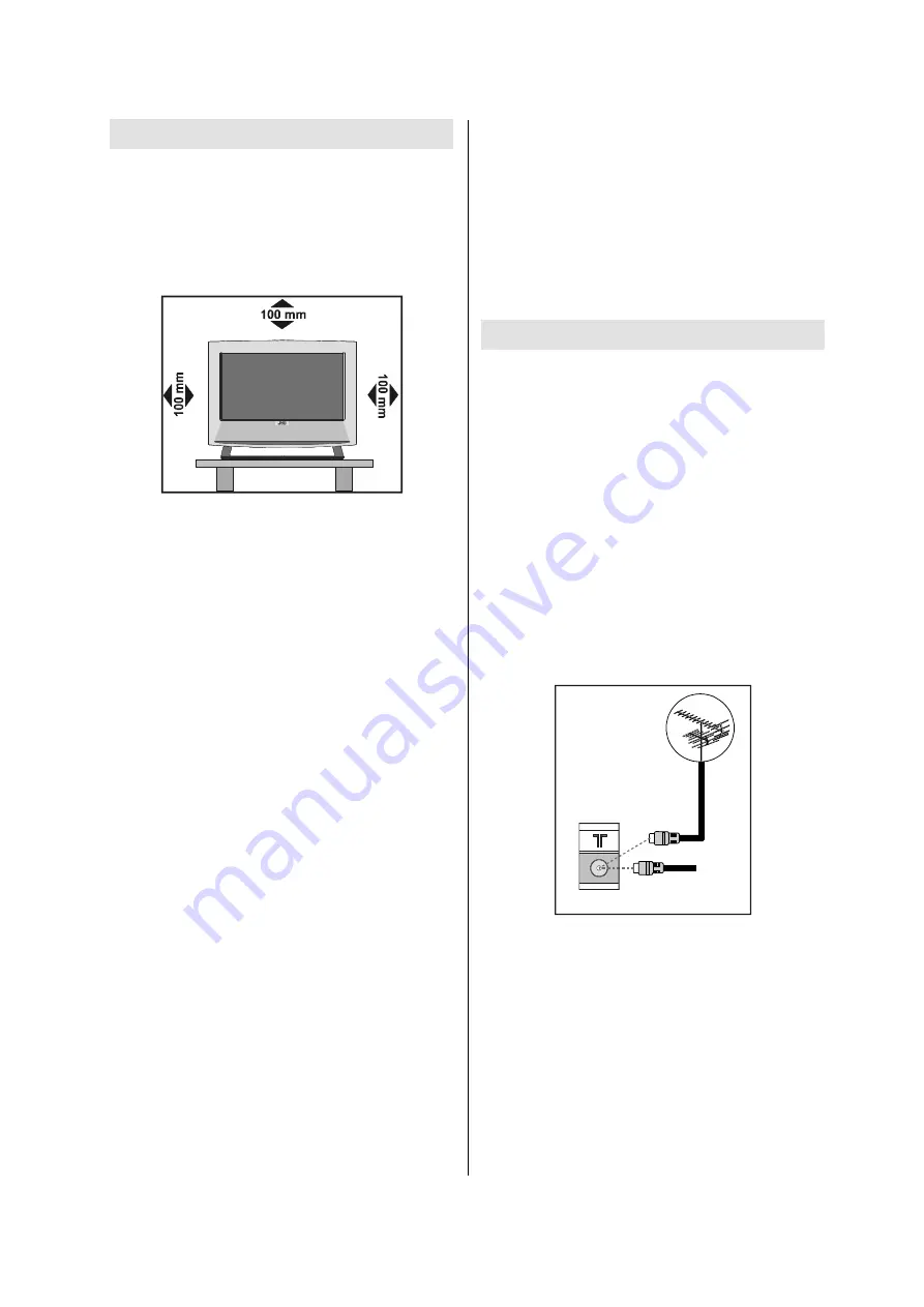
Install Display on solid horizontal surface such
as a table or desk.
For ventilation, leave a space of at least 10 cm
free all around the set. To prevent any fault
and unsafe situations, please do not place
any objects on top of the set.
Features
It is a remote controlled colour television and
PC monitor.
100 programmes from VHF, UHF bands or
cable channels can be preset.
It can tune cable channels.
Controlling the TV is very easy by its menu
driven system.
It has 2 pieces of Euroconnector
sockets
for
external devices (such as video, video
games, audio set, etc.)
Nicam stereo sound system.
Multilanguage OSD.
Teletext (Fastext, 7 pages).
It is possible to connect headphone.
A.P.S. (Automatic programming system)
All programmes can be named.
Forward or backward automatic tuning.
Sleep timer.
Child lock.
Auto, Full, Regular, Panoramic, 14:9 Zoom,
16:9 Zoom,16:9 Zoom Subtitle modes.
Automatic sound mute when no transmis-
sion.
When no valid signal is detected, after 5 min-
utes the TV switches itself automatically to
stand-by mode.
NTSC Playback.
PLL (Channel Search)
TV Picture in PC (if PC input available).
PC input (Support Up to
1366 x 768)
Audio Lineout
Before Switching on your TV
Power connection
IMPORTANT:
The TV set is designed to oper-
ate on
220-240V AC, 50 Hz.
After unpacking, allow the TV set to reach the
ambient room temperature before you con-
nect the set to the mains.
Connections to the RF input
socket
Connect the aerial or cable TV plug to the RF
input socket located at the back of the TV
and connect the cable plug coming out from
the TV out socket located at the devices (VCR,
DVB etc.) to this socket as well.
795($53$1(/
&$%/(79
How to connect other devices
IMPORTANT:
Switch off the TV before connect-
ing any external device.
Sockets for external connections are at the
back of the TV. For connection of other devices
via Euroconnector refer to the manuals of the
related devices.
Summary of Contents for LT-26B60BU
Page 60: ... No YA352 3 13 PACKING 5 6 7 7 8 7 9 3 2 ...
Page 72: ... No YA352 2 17 2 18 No YA352 MAIN PWB ASS Y 8 8 VE 20224628 MAIN PWB CIRCUIT DIAGRAM 8 8 ...
Page 75: ... No YA352 2 23 2 24 No YA352 TOP PATTERN DIAGRAMS MAIN PWB PATTERN SOLDER SIDE ...
Page 76: ... No YA352 2 25 2 26 No YA352 TOP MAIN PWB PATTERN PARTS SIDE ...
Page 77: ... No YA352 2 27 2 28 No YA352 TOP POWER PWB PATTERN SOLDER SIDE ...
Page 78: ... No YA352 2 29 2 30 No YA352 TOP POWER PWB PATTERN PARTS SIDE ...


