ENGLISH
- 23 -
PC Mode
Installation
Power off both Computer and Display before
making any connections.
Set your PCs resolution correctly before con-
necting to the TV. See the table in
page 29
for
supported modes.
Use a D-SUB cable to connect the TVs PC
input to the computers RGB output termi-
nal. If you want to listen to the sound from the
computer, use an audio cable to connect the
PC AUDIO IN to the computers sound out-
put terminal.
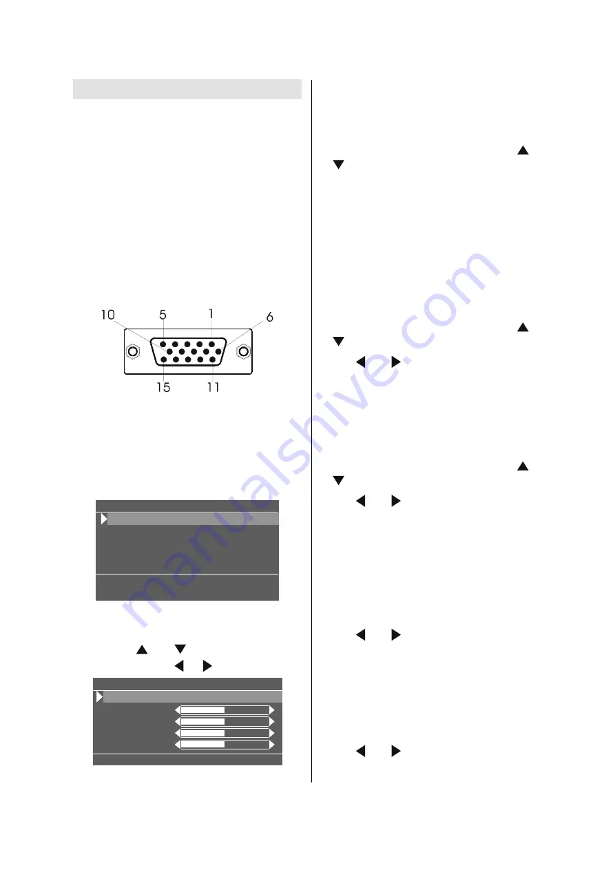
3LQ0LQL'6XE&RQQHFWRU
Tighten the screws of the Display cable until
the connectors are fastened securely (fin-
ger-tighten only).
Main Menu in PC mode
Enter the main menu by pressing the
MENU
button on the remote control.
3&0HQX
3&3LFWXUH3RVLWLRQ
3&3LFWXUH
6RXQG
3,33LFWXUH
[
+N+]9+]
6RXUFH
PC Picture Position Menu
In the Main menu, select
PC Picture Posi-
tion
using or button, then enter the
menu by pressing / or
OK
buttons.
3&3LFWXUH3RVLWLRQ
$XWR3RVLWLRQ
+RUL3RVLWLRQ
9HU 3RVLWLRQ
'RW&ORFN
&ORFN3KDVH
Auto Position
If you shift the picture horizontally or vertically
to an unwanted position, use this item to put
the picture into correct place automatically.
Select Auto position item by using or
buttons.
Press
OK
button.
Press
MENU
button or
BACK
button to store
the value.
Warning:
Auto position adjustment recom-
mended to be done with the full screen image
for the proper adjustment.
Horizontal Position
This item shifts the image horizontally to right
hand side or left hand side of the screen.
Select Hor. Position item by using or
button.
Use or button to adjust the value.
Press
MENU
button or
BACK
button to store
the value.
Vertical Position
This item shifts the image vertically towards
the top or bottom of the screen.
Select Ver. Position item by using or
button.
Use or button to adjust the value.
Press
MENU
button or
BACK
button to store
the value.
Dot Clock
Dot Clock adjustments correct interference
that appear as vertical banding in dot inten-
sive presentations like spreadsheets or para-
graphs or text in smaller fonts.
Use or button to adjust the value.
Clock Phase
Depending on the resolution and scan fre-
quency that you input to the TV Set, you may
see a muddy or noisy picture on the screen. In
such a case you can use this item to get a
clear picture by trial and error method.
Use or button to adjust the value.
Summary of Contents for LT-26B60BU
Page 60: ... No YA352 3 13 PACKING 5 6 7 7 8 7 9 3 2 ...
Page 72: ... No YA352 2 17 2 18 No YA352 MAIN PWB ASS Y 8 8 VE 20224628 MAIN PWB CIRCUIT DIAGRAM 8 8 ...
Page 75: ... No YA352 2 23 2 24 No YA352 TOP PATTERN DIAGRAMS MAIN PWB PATTERN SOLDER SIDE ...
Page 76: ... No YA352 2 25 2 26 No YA352 TOP MAIN PWB PATTERN PARTS SIDE ...
Page 77: ... No YA352 2 27 2 28 No YA352 TOP POWER PWB PATTERN SOLDER SIDE ...
Page 78: ... No YA352 2 29 2 30 No YA352 TOP POWER PWB PATTERN PARTS SIDE ...


