background image


Rev A 


Page 1 

wiJAC2-T32 

Wireless Intercom System with Transceiver Connection 

 - 3 User - Europe


Introduction  

This manual contains the operating instructions for the wiJAC2-T32 Wireless Intercom System with Transceiver 
Connection - 3 User - Europe.  

The diagram below describes the naming method for the different systems. 


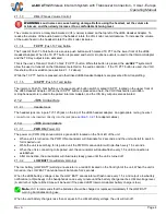
wiJAC2-T 3 2


The 

wiJAC2-T32

 consists of up to three JB66-002 Wireless Aircraft Headset Adapters, and one JB67-002 Wireless 

Aircraft Intercom adapter.  


RF output power is 21 dBm (125 mW peak) 


Channel frequencies 


9 = 1.881792 GHz  

8 = 1.883520 GHz 

7 = 1.885248 GHz 
6 = 1.886976 GHz 

5 = 1.888704 GHz 


4 = 1.890432 GHz 

3 = 1.893888 GHz 

2 = 1.896616 GHz 
1 = 1.895616 GHz 

0 = 1.897344 GHz 

Only paired units will operate together (see 

section 1.3

) 

System operating information is i

section 4

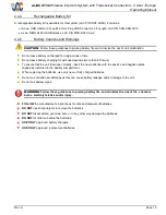
WARNING

JAC recommends that no battery-operated device should be relied upon as the sole 

method of communication in cases where there is potential risk to life or limb.


1.1 

Unpacking 

Unpack the 

wiJAC2

™ box carefully, and ensure that it contains the following: 

  three ea. Wireless Aircraft Headset Adapter, JAC P/N JB66-002 

  one ea. Wireless Aircraft Intercom Adapter, JAC P/N JB67-002 

  one ea. Headset Adapter Cable, JAC P/N CAB-HSET-0001 

  three ea. Audio Panel Intercom Adapter Cable (10pin Hirose plug to U174 plug), JAC P/N CAB-WJ2-0004 

  one ea. 

wiJAC2-T32

 User Quick Start Guide, JAC P/N DOC-GUID-WI2TX2 

1.2 

Verify Operating Region 

The 

wiJAC2-T32

 Wireless Intercom System operates using radio frequencies that are authorized by government 

regulatory agencies. Ensure the region in which you are operating the units matches the region marked on a label on 

the back of each unit. 

Number of Headsets 

in the System (2 – 4) 


Operating Region: 

1 = N America 

2 = Europe 

System Type:  

T = Transceiver 


Summary of Contents for wi JAC2-T32

Page 1: ...reless Intercom System with Transceiver Connection 3 User Europe Operating Manual Rev A Jupiter Avionics Corporation 1959 Kirschner Road Kelowna BC Canada V1Y 4N7 Tel 1 778 478 2232 Toll Free 1 855 478 2232 www jupiteravionics com ...

Page 2: ...rized commercial distribution of this manual is strictly prohibited Except as described above no part of this manual may be reproduced copied transmitted disseminated downloaded or stored in any storage medium for any purpose without the express prior written consent of JAC RECORD OF REVISIONS Revision Rev Date Description ECR A Jul 2020 Initial release Serial number 1001 and higher 7499 Prepared ...

Page 3: ...th JB66 and JB67 9 2 4 1 Inserting or Replacing the Batteries 9 2 4 2 Charging Batteries in the Unit 9 2 4 3 Charging Operation via Battery Charger 9 2 4 4 Rechargeable Battery Kit 10 2 4 5 Battery Cautions and Warnings 10 3 Connecting the wiJAC2 System 11 3 1 wiJAC2 T32 System with a Transceiver 12 3 2 wiJAC2 T32 System connected to Aircraft Audio System 13 3 3 wiJAC2 Set up and Connection 14 3 3...

Page 4: ...ion 4 WARNING JAC recommends that no battery operated device should be relied upon as the sole method of communication in cases where there is potential risk to life or limb 1 1 Unpacking Unpack the wiJAC2 box carefully and ensure that it contains the following three ea Wireless Aircraft Headset Adapter JAC P N JB66 002 one ea Wireless Aircraft Intercom Adapter JAC P N JB67 002 one ea Headset Adap...

Page 5: ...ter and up to three JB67 002 Intercom Adapters Only paired units will operate together Refer to the Pairing Instructions in section 3 4 1 2 The wiJAC2 T32 Components The main components of the wiJAC2 T32 are three JB66 002 Headset Adapters and the JB67 002 Intercom Adapter The headset is not included Headset Adapter Cable CAB HSET 0001 Audio Panel Adapter Cable see section 3 3 2 1 JB66 002 Headset...

Page 6: ...en turn off as the JB66 turns off or when the ON OFF button is released 2 1 1 2 VOX Voice Operated Switch The Voice Operated Switch control is a rotary knob marked VOX located on the top right of the JB66 Headset Adapter To reduce the level of the sound needed to route the microphone audio to the Intercom Adapter turn the VOX knob counterclockwise ccw To increase the level of the sound needed to r...

Page 7: ...rophone audio is routed to the paired Intercom Adapter and the ICS Key output is also activated 2 1 2 JB66 Connectors 2 1 2 1 Headset Jack The headset jack is a 4 pole TJT 120 jack on the top of the JB66 headset adapter An appropriate mating headset connector can be inserted directly into the jack see section 3 3 2 1 for adapter cables 2 1 3 JB66 Annunciators 2 1 3 1 PWR ON Power On The power on P...

Page 8: ... battery compartment The Charging annunciator CH is a red LED that will illuminate when the batteries are being charged at the maximum charge current and the Full Charge F annunciator is a green LED that will illuminate when the batteries are fully charged 2 1 4 3 Controls These buttons are recessed to prevent accidental activation The Boot BT and Reset RST buttons should only be activated by qual...

Page 9: ... 10 pin Hirose jack on the top of the JB67 intercom adapter for use with a U 174 U or U93A U type intercom plug see section 3 3 2 1 for adapter cables 2 2 3 JB67 Annunciators 2 2 3 1 PWR ON Power On The power on PWR ON annunciator is a green LED located on the front left of the unit When a unit is turned on the PWR ON annunciator will illuminate for 2 seconds and the unit will start to search for ...

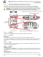
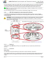
Page 10: ...remove the battery cover by unfastening the thumbscrew on the rear of the unit and raising the top of the cover until it can be lifted clear of the retaining tabs CAUTION To prevent potential damage or loss of function the internal adjustments controls and CONFIG port information italicized should only be used by qualified technical personnel Contact your installing agency for any required changes...

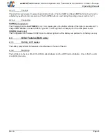
Page 11: ...ed POWER is a 2 1 mm coaxial jack on the bottom left side of the battery compartment To charge NiMH batteries connect a USB to Type M 2 1 mm Plug from the Charging Port to a USB power source CONFIG Mode Select The Configuration Port marked CONFIG on the bottom right side of the battery compartment is for factory use only 2 3 Other Features Both units 2 3 1 Battery Lid Release The battery compartme...

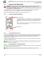
Page 12: ...lots Remove the batteries and insert new or fully charged batteries matching the polarity marked on the battery holder Retaining tabs 2 4 2 Charging Batteries in the Unit To charge rechargeable batteries in the unit connect the Charging Port to a USB power source using the USB to 2 1 mm male cable CAB USB 0013 see section 2 4 4 If turned on during charging the unit draws its power from the chargin...

Page 13: ...more than 48 hours To ensure that the unit functions correctly insert the new batteries with the positive and negative poles aligned as indicated in the battery compartment When replacing the batteries use only new or fully charged batteries Do not mix old and new batteries as this can cause battery leakage and or damage to the unit Do not mix battery types WARNING Follow these guidelines to prolo...

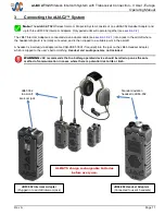
Page 14: ...lly connected and is then clipped to a suitable point in the aircraft A headset is inserted via adapter cable CAB HSET 0001 if required into the jack on the JB66 Headset Adapter which is clipped to the user s belt or clothing Headset and audio panel are not included WARNING JAC recommends that no battery operated device should be relied upon as the sole method of communication in cases where there...

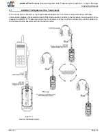
Page 15: ...d Headset Adapters are in an intercom loop which allows full duplex communication between the operators of each JB66 Each operator can listen to the transceiver receive audio and by pressing the JB66 TX PTT button can transmit on the transceiver When one JA66 is transmitting all other JB66 mics will be muted but the operators can hear the radio sidetone Figure 3 1 Non Aircraft Radio System ...

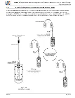
Page 16: ...ked Headset Adapters are in an intercom loop which allows full duplex communication between the operators of each JB66 Each operator hears the aircraft ICS audio and by pressing the TX PTT button on a JB66 can route the mic audio to the aircraft audio system ICS When one JB66 TX PTT button is pressed all other JB66 mics will be muted but the operators can listen to the conversation Figure 3 2 Airc...

Page 17: ...urn on the JB66 Headset Adapters and the JB67 Intercom Adapter On both units the PWR ON and LOW BATT annunciators will illuminate for two seconds When a unit is turned on the PWR ON annunciator will illuminate for 2 seconds and the unit will start to search for units it is paired with While the unit is searching for its paired units the PWR ON annunciators will triple flash every 1 5 seconds When ...

Page 18: ...ibed in the following steps 1 Turn off the JB67 and previously paired JB66 2 Turn on the JB67 The JB67 enters the standby mode Power Annunciator blinks in sets of two or three flashes If the Power Annunciator stays on continuously the JB66 is still powered on and connected to the JB67 Turn off the JB66 3 On the JB67 press and hold the Pair Switch 4 seconds until the Power and Low Battery Annunciat...

Page 19: ...ected to the JB67 Please turn off the JB66 3 On the JB67 002 press and hold the Pair Switch 4 seconds 4 When the JB67 Power and Low Battery annunciators begin blinking rapidly press the JB67 Power Button 5 Release the Pair Switch and Power Button The JB67 enters the purge mode Power Annunciator blinks in sets of three flashes Wait for the JB67 to finish purging all paired JB66s from its memory app...

Page 20: ... 1 4 Live Speaking Operation To use the JB66 Headset Adapter so that the microphone audio is always turned on adjust the VOX control fully counter clockwise 4 1 5 Low Battery Warning When the unit s battery charge is low the LOW BATT annunciator will triple flash every 1 5 seconds When the JB66 Headset Adapter battery charge is low a triple beep will be heard in the headset once every minute Note ...

Page 21: ...wer the radio frequency RF power required for connection This will increase the battery life Obstacles between the Headset Adapter and Intercom Adapter VOL Minimising the aircraft metal structures human bodies cargo and other obstacles between the units will reduce the RF power needed for connection and increase the battery life Charge capacity of the batteries installed The higher the capacity of...

Reviews: