


Adjustment Procedure
Results of Improper Adjustment
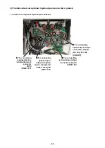
Configuration of lubrication mechanism parts is as shown in the
drawing.
1. Oil tank
Pull up the oil tank
❶
straight from the float case guide
❷
to
take it out.
Remove and adjust the lubrication pipe
❸
and others within the
permissible range where they can be stretched.
The float case guide
❷
has a notch groove with orientation.
Push it straight along the groove to make a joint.
(Push it until there is a feeling of coupling with a click sound.)
2. Float
The float
❹
has an orientation.
Insert it in the oil tank
❶
with its flat plane positioned on the right
as seen from worker side.
Be careful not to bend the bar of the float
❹
.
Description
Part No.
Float
❹
40172430
3. Float case guide
Put the float case guide
❷
in the guide groove section of the
peep window
❺
and fix it to the bed.
4. Peep window
Remove the window plate located behind the arm. It is fixed to
the arm.
5. Oil filter
The oil filter
❻
can be cleaned after removing the lubrication
pipe fixing ring
❼
and pulling out the lubrication pipe
❸
.
* When you disassemble it, remove two setscrews for an oil tank
and put it out downward. It is removed by unit in such a state as
shown in the Figure B
– 145 –


