


6
.
Electrical component and the like
(
1
)
Construction of a control box and how to remove a board
1
)
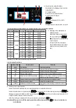
Construction of a control box
The control box consists of the following three kinds of board assemblies and the board incorporated into
the electrical box varies depending on the specifications and places of destinations.
❶
❷
❸
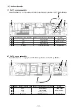
❶
FLT-S board assembly
FLT-T board assembly
❷
CTL board assembly
CTL-D board assembly
❸
PWR board assembly
PWR-CE board assembly
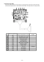
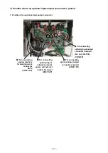
2) How to remove the CTL board assembly
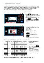
3) How to remove the PWR board assembly
When you remove eight setscrews
❹
shown in
the left Figure, you can remove the CTL board
assembly
❷
.
* When you remove the CTL board assembly
❷
,
do it after removing the connector.
* It is necessary to remove the FLT-T board as-
sembly
❶
first according to the specification of
the three phases.
CTL / CTL-D board asm.
❹
The construction of the PWR board assembly
❸
allows you to remove the PWR board assembly with-
out removing the CTL board assembly
❷
, but it is
necessary to follow the following procedure.
1. Remove the connector connected to the PWR
board assembly
❸
.
2. Remove the FG lines for of a principal axis motor,
a horizontal feed motor, and the vertical feed mo-
tor.
3. Remove the CN31, CN35, and CN62 of the CTL
board assembly
❷
.
4. Remove the CN2 of the FLT board assembly
❶
.
5. Remove four setscrews for the PWR board as-
sembly
❺
.
6. Draw the PWR board assembly
❸
upward to the
extent of 5 mm and slide it downward to remove it.
❺
PWR / PWR-CE board asm.
* The PWR board
❸
has a groove for anti-drop, so it is not possible to slide it downward only by removing
a screw.
– 122 –


