background image

目  次

!

. 仕様 ....................................................................................................................1

@

. セットアップ .....................................................................................................2

 [1] AE-9/AE-16 ......................................................................................................................2

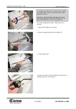
  1. チューブ支えの取り付け ...............................................................................................................2

  2. センサ取付台の仮止め ...................................................................................................................2

  3. 窓板の取り外し ...............................................................................................................................3

  4. ファイバーセンサの取り付け .......................................................................................................3

  5. エアーチューブの配管 ...................................................................................................................5

  6. 窓板の取り付け ...............................................................................................................................6

 [2] AE-12/AE-17 ...................................................................................................................7

  1. 固定メス台ストッパーの取り外し ................................................................................................7

  2. 窓板の取り外し ...............................................................................................................................8

  3. ファイバーセンサの取り付け .......................................................................................................9

  4. エアーチューブの配管 ................................................................................................................11

  5. 窓板の取り付け ............................................................................................................................12


[3]  電磁弁の取り付け .............................................................................................................12

 [4] センサアンプ・検知スイッチの取り付け ......................................................................13

  1. センサアンプの取り付け ............................................................................................................13

  2.  検知スイッチの取り付け ............................................................................................................17

  3. コードの配線 ...............................................................................................................................18

#

. 感度調整 .........................................................................................................20

  1. センサアンプの機能の確認 ........................................................................................................20

  2.  センサアンプの感度調整値確認 .................................................................................................21

  3. ファイバーセンサの位置調整 ....................................................................................................22

  4. エアーノズルの位置確認 (AE-9/AE-16) ...............................................................................24

$

. 動作と設定 .....................................................................................................25

  1. 動作 ...............................................................................................................................................25

  2. 設定 ...............................................................................................................................................26

%

. ボビンへの糸の巻き方 ..................................................................................28

^

. 装置における現象と原因・確認又は対策 ...................................................29

&

. 各コードの配線表 ..........................................................................................30

 32 

(3) 電磁弁コード / 

Solenoid valve cord

(4) 電磁弁中継コード (SC-510 で使用 )/ 

Solenoid valve connecting cord (to be used with SC-510)

CN124-1

CN124-1

1
2
3
4

CN7

1

2

2
1

CN7

線色

終了点

備考

CN7-2

+ 24 V

CN7-1

エアーブロー(−)

Color of cord

Ending point

Remarks

Red

CN7-2

+24V

Black

CN7-1

Air blow( – )

線色

開始点

終了点

備考

CN7-2

CN124-1-1

+ 12 V

CN7-1

CN124-1-2

OUT

Color of cord Starting point Ending point

Remarks

White

CN7-2

CN124-1-1

+12V

Black

CN7-1

CN124-1-2

OUT

(4)AE 中継コード (SC-922 で使用 )/ 

AE junction cord (to be used with SC-922)

SC-510 用 /SC-922 用 / 

For use with SC-510/SC-922

線色

開始点

終了点

備考

CN103-1

CN51-4

AESW

CN103-2

CN51-15

AESW LED

CN103-3

CN51-1

0V

CN103-4

CN51-12

+24V

CN104-2

CN51-5

AE SENSOR1

CN104-3

CN51-1

0V

CN104-5

CN51-6

AE SENSOR2

CN7-1

CN51-16

AE AIR BLOW

CN7-2

CN51-12

+24V

Color of cord

Starting point

Ending point

Remarks

Black

CN103-1

CN51-4

AESW

White

CN103-2

CN51-15

AESW LED

Green

CN103-3

CN51-1

0V

Red

CN103-4

CN51-12

+24V

Yellow

CN104-2

CN51-5

AE SENSOR1

Brown

CN104-3

CN51-1

0V

Blue

CN104-5

CN51-6

AE SENSOR2

Black

CN7-1

CN51-16

AE AIR BLOW

White

CN7-2

CN51-12

+24V

CN104

4  3

2  1

CN103

CN7

4      3

2      1

2

1

CN51

12                                    22

1                                     11

Summary of Contents for AE-12

Page 1: ...CTIONS in the Instruction Manual the LU 2200N series before putting the machine into service when this device is installed to the LU 2200N series In addition to emphasize the AE 9 AE 12 AE 16 and AE 1...

Page 2: ...124 1 1 12V Black CN7 1 CN124 1 2 OUT 4 AE SC 922 AE junction cord to be used with SC 922 SC 510 SC 922 For use with SC 510 SC 922 CN103 1 CN51 4 AESW CN103 2 CN51 15 AESW LED CN103 3 CN51 1 0V CN103...

Page 3: ...e solenoid valve 12 4 Installing the sensor amplifier and the detecting switch 13 1 Installing the sensor amplifier 13 2 Installing the detecting switch 17 3 Wiring the cord 18 ADJUSTING THE SENSITIVI...

Page 4: ...eful of handling the fiber sensor Actions such as forcibly drawing bending giving a shock etc will cause damage to the fiber sensor So be careful 30 Ending point Remarks CN124 3 1 12V CN124 3 2 LED CN...

Page 5: ...e bobbin thread remaining amount detecting device with screw 6 2 Replace the counter knife base attached to the hook shaft base with the counter knife base for the bobbin thread remaining amount detec...

Page 6: ...emove the fixing screws in window plate 1 2 Turn window plate 1 by 90 to move it in the right direction 3 1 3 Pull window plate 1 to this side and remove it 5 1 4 1 1 1 2 1 3 CAUTION Be very careful o...

Page 7: ...4 6 5 3 Draw out fiber sensor 4 near to the hook and attach it to sensor installing base 5 with screw 6 4 1 7 4 Insert sensor protection tube 1 into tube support 7 1 250mm 1 3 Incase of attaching the...

Page 8: ...tion such as moving knife and the like 2 1 4 3 41 1 Case of 1 needle 9 8 2 Case of 2 needle 2 Case of 2 needle 4 7 5 6 26 1 SC 510 1 4 ON 4 2 2 1 2 5 57 3 3 4 6 1 2 4 1 2 OFF 0 4 3 4 0 2 1 Pressing sw...

Page 9: ...in the presser lifter cylinder into presser lifter lever 2 2 3 2 Move window plate 3 in the left direction 3 2 A 4 3 At this time adjust so that section A of the presser lifter lever 2 comes under kn...

Page 10: ...1 In addition adjust so that the air nozzle does not come in contact with the driving section such as the moving knife and the like Be careful that the hole of air nozzle 2 is not broken 5 7 2 4 8 400...

Page 11: ...s of air cylinder 2 3 Loosen nut 3 and remove hinge screw 4 4 Remove all of the fixing screws of air cylinder 5 5 6 7 5 Loosen fixing screws 7 and remove air cylinder installing base 6 2 1 4 3 5 6 7 6...

Page 12: ...fiber sensor be sure to perform the adjustment after disconnecting the connector for the pedal lever of the control boxof the sewing machine from the control box After completion of the adjustment re...

Page 13: ...machine bed and draw them out near the hook Caution Be careful that the fiber sensor is not bent 5 Install counter knife base stopper 5 with installing screws 1 Here perform the adjustment of the posi...

Page 14: ...2 9 5 Bundle air tube 1 and sensor protection tube 2 with clip band 9 so that the tubes do not come in contact with the driving section of moving knife and the like 5 6 4 3 12 12 2 8 9 7 20 ADJUSTING...

Page 15: ...the reverse order of the removing procedure of the window plate 3 Installing the solenoid valve 1 6 2 1 2 3 3 4 5 1 Stop the air supply to regulator 6 2 Attach solenoid valve 2 to regulator installing...

Page 16: ...way joint 9 to joint 7 of the regulator 7 6 7 Return regulator 6 to its home position to let the air in 9 8 7 0 6 4 Installing the sensor amplifier and the detecting switch 1 Installing the sensor am...

Page 17: ...ensor amplifier so that the sensor amplifier cord is located on the hanndwheel side of the sewing machine 2 A 6 In case of 2 needle place sensor amplifier 6 which plane A of the installing metal fitti...

Page 18: ...cutter 3 Insert the fiber sensor cord into the smallest hole in F cutter 3 and press down the cutter blade at one stroke to cut the fiber sensor cord Caution When cutting the fiber sensor perform cutt...

Page 19: ...case cover 6 of the sensor amplifier and tilt lock lever 7 on sensor inserting hole 8 side 2 6 7 8 9 4 A 5 B 9 Insert black adapter 4 into inserting hole A and gray adapter 5 into inserting hole B Ca...

Page 20: ...12 AE 17 1 2P 0 For the AE 12 17 route detecting switch cord 1 in the same manner as the sensor protection tube and fix it with bundled with clip bands 0 to prevent it from interfering with the drivin...

Page 21: ...1 Jumper W1 W2 W5 W6 W3 W4 3 4 5 6 3 4 1 2 2 4 6 1 3 5 Setting position 3 Wiring the cord 5 WARNING Turn OFF the power switch to the sewing machine so as to prevent accidents caused by abrupt start of...

Page 22: ...cord for AE to CN51 of the SC 922 2 Connect connector 4P 1 of the junction cord for AE to the detecting switch cord 3 Connect connector 6P 2 of the junction cord for AE to the sensor amplifier cord 4...

Page 23: ...4 2 1 2 When operation mode 1 is not L perform the adjustment by the procedures of 2 1 to 2 4 below 2 1 Turn switch 2 from RUN to SET 2 2 3 3 2 2 Press button BLACK 3 for three seconds to indicate SEL...

Page 24: ...ange of the sensitivity adjustment value is completed the state becomes as described in the aforementioned step 3 L 1 S 2 Flash Sensitivity adjustment value 2 3 4 SET RUN SET RUN 10 3 7 1 3 Slowly ins...

Page 25: ...nector for the pedal lever be sure to perform the operation after turning OFF the power to the sewing machine When performing the adjustment of the sensitivity of the fiber sensor perform the adjustme...

Page 26: ...ne bobbin for detection 5 around which bobbin thread is not wound and set it to the inner hook so that plane sections 6 reflecting planes face hole 2 of the inner hook 3 Turn ON the power of the sewin...

Page 27: ...the step 4 quantity of light value 8 of the sensor amplifier at section B where outer hook 7 does not cover hole 2 of the inner hook Check that the minimum quantity of light value in the section is 40...

Page 28: ...machine is to be stopped or not when the detecting device detects that bobbin thread has run out has to be specified by means of the sewing machine controller 2 When you desire to replace the bobbin r...

Page 29: ...lay section 6 1 or 2 For the contents of the function refer to the list below 4 After setting press switch 1 or switch 2 and turn OFF the power Caution Bobbin thread remaining amount detection functio...

Page 30: ...ng If the display shown on the screen does not change turn the power supply OFF and carry out operation 1 again Caution Be sure to re turn ON the power switch when one or more seconds have passed afte...

Page 31: ...bbin winder In case of the single bank bobbin set the side with hole 2 to this side Caution Remaining amount detection cannot be performed unless the side with hole 2 is set to this side 2 Wind bobbin...

Page 32: ...NOMENA CAUSES AND CHECKING OR CORRECTIVE MEASURES WITH REGARD TO THE DEVICE 1 2 3 1 2 3 4 5 6 1 1 1 1 2 3 4 5 6 1 1 2 WARNING Turn OFF the power before starting the work so as to prevent accidents cau...

Page 33: ...point Red Switch Blue Black Switch Yellow NO Orange NO CN123 3 CN124 3 1 2 3 4 1 2 3 4 CN123 3 CN124 3 WIRING TABLE OF RESPECTIVE CORDS SC 510 For the SC 510 SC 922 For the SC 922 Ending point Remark...

Page 34: ...d be used CONTENTS SPECIFICATIONS 1 SET UP 2 1 AE 9 AE 16 2 1 Piping the fiber sensor 2 2 Temporarily installing the sensor installing base 2 3 Removing the window plate 3 4 Installing the fiber senso...

Page 35: ...h SC 922 SC 510 SC 922 For use with SC 510 SC 922 CN103 1 CN51 4 AESW CN103 2 CN51 15 AESW LED CN103 3 CN51 1 0V CN103 4 CN51 12 24V CN104 2 CN51 5 AE SENSOR1 CN104 3 CN51 1 0V CN104 5 CN51 6 AE SENSO...

Page 36: ...INSTRUCTION MANUAL AE 9 AE 12 AE 16 AE 17 AE 9 AE 12 AE 16 AE 17 LU 2200N LU 2200N AE 9 AE 12 AE 16 AE 17 LU 2200N CAUTION This Instruction Manual is intended for the AE 9 AE 12 AE 16 and AE 17 Read...

Reviews: