


B-151
Appendix B
Menu List and Materials
1
2
3
4
5
6
7
8
9
10
11
12
13
14
15
16
17
18
19
20
21
22
23
APP B
24
25
27
APP C
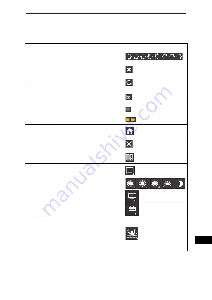
B.9 List of Icons/Icon Buttons
The icons/icon buttons displayed in this equipment are listed below.
No.
Name
Functional outline
Displayed image
1 Active
indicator
Indicates that the computer is
processing by an animation.
2
Delete
Deletes the item.
3
Check again
Checks the contents being displayed
again.
4
Setting mark
Displayed when the operation is valid.
(E.g., Latitude and longitude offset of
chart)
5
Drive
Displayed at the left of the name
when a drive is selected.
6
Folder
Displayed at the left of the name
when a folder is selected.
7
Home
Changes from the currently displayed
screen to the home screen.
8
Close
Closes the dialog box.
9
Date selection Displays the calendar picker.
10 Dialog
box
display
Opens another dialog box. (E.g.,
Route selection dialog)
11 Day/Night
Displays the state of the current
Day/Night setting by an icon.
12 Screen
brightness
Enables adjustment of the screen
brightness.
13 Panel
brightness
Enables adjustment of the brightness
of operation unit.
14 MOB
Starts the MOB (Man Over Board)
mode.
In the MOB mode, a symbol display of
the position of the sailor falling over
board and a dotted like connecting it
to the own ship are displayed
graphically.
Summary of Contents for ECDIS
Page 2: ......
Page 10: ...Contents 8 ...
Page 40: ...Section 17 Adjusting and Setting up Equipment for Services 17 30 ...
Page 132: ...Section 20 Failures and After Sale Services 20 20 ...
Page 152: ...Section 22 Specifications 22 18 ...
Page 212: ...Appendix B Menu List and Materials B 32 B 1 16 Code Input Password ECDIS CONNING ...
Page 368: ...Appendix B Menu List and Materials B 188 ...
Page 369: ......


