


41
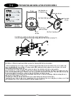
The following preparations are suggested for use with JR
®
radio systems. However, these procedures are applicable to most other
brand radio systems. These suggested adjustments are necessary to insure correct installation and attachment of the control linkages
and servo horns.
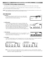
TRANSMITTER PREPARATION
RECEIVER FLIGHT PACK PREPARATION
SERVO HORN INSTALLATION SUGGESTIONS
1. Set all trim levers, knobs, and switches to the neutral or
zero positions.
2. Turn the transmitter power switch to the On position.
3. Reset all functions and input values of your computer
radio system to the factory preset position.
4. Move the throttle/collective control stick to the center or half
stick position. Next slide the throttle trim lever to the full low
position.
1. With the transmitter still on, slide the receiver switch to its
On position. All servos should move to the neutral or
center position.
2. Check that all servos operate with the appropriate
control stick.
3. Rest the throttle stick to the center position, making sure
the throttle trim is still at low.
4. Turn off the receiver switch first, followed by the transmitter.
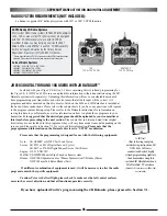
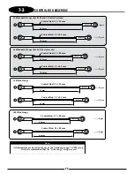
For proper operation, it’s important that the servo horns are
positioned on the servos in the “exact” neutral position. Although
most computer radio systems offer a sub-trim feature, it is
suggested that the servo horns be manipulated on the servos to
achieve the “exact” neutral settings.
Since the servo output spline on a JR system has an odd number
of teeth (21), it’s possible to reposition the servo arm on the servo
at 90° intervals to achieve the proper neutral attachment of the
servo horn.
Once the correct arm of the servo horn has been established,
it’s suggested that the remaining unused arms be removed from
the servo horn as shown in the installation diagrams in the
following section.
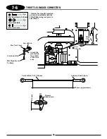
It will also be necessary to enlarge the appropriate hole in the servo
horn slightly to allow correct installation of the steel control balls to
the servo horn.
RADIO SYSTEM PREPARATION
Summary of Contents for Vigor CS
Page 64: ...64 E A C D G F DECAL PLACEMENT ...
Page 65: ...65 B 3 2 5 1 DECAL PLACEMENT ...


