


36
............. 1 pc
................. 1 pc
..................... 1 pc
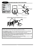
Flat Head Screw, 2 x 8 mm
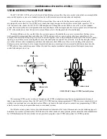
Steel Joint Ball
Hex Nut, 2 mm
Red
Flat Head Screw, 2 x 8 mm
Steel Joint Ball
Hex Nut, 2 mm
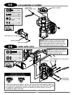
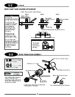
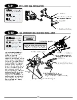
Attach the steel joint ball to
the outside hole as shown.
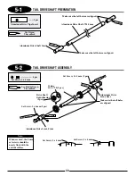
5-11
STEEL JOINT BALL INSTALLATION
5-12
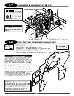
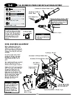
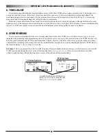
TAIL DRIVE SHAFT/TAIL GEAR BOX INSTALLATION
Red
4 pcs
Set Screw, 4 x 4 mm (4 pcs)
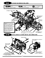
*Apply a coating of light oil to
the O-rings of the drive shaft
guide bearing.
Red
Red
4 pcs
Set Screw, 3 x 3 mm (4 pcs)
Socket Head Bolt, 3 x 12 mm
* Do not tighten completely until
the gear box has been positioned correctly.
Set Screw, 4 x 4 mm
.......................... 4 pcs
.......................... 4 pcs
Set Screw, 3 x 3 mm
Socket Head Bolt, 3 x 12 mm
............. 1 pc
Use Red Threadlock
Tail Drive Shaft Assembly
Tail Gear Box Assembly
* Tighten after gear box has been aligned.
Attach the tail drive shaft to the
tail gear box as shown using the
4–4 mm set screws (use
Threadlock). Please leave a very
slight space between the drive shaft
and the bearing of the tail gear box.
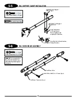
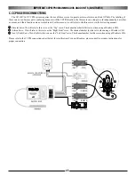
Next, apply a light coating of oil to
the drive shaft guide O-rings and
install the assembly into the tail
boom. To allow the tail gear box to
be fully inserted into the boom, it
may be necessary to rotate the
front bevel pinion gear so the drive
shaft can engage into the coupler.
Level the tail output shaft of the
tail gear box so that it is 90
°
to the
main rotor shaft, and lock the tail
gear box in place using the 3 mm
socket head bolts and 3 mm set
screws as shown.
Vertical
Fin
Note:
It will be neccessary to loosen the 4 bolts
holding the vertical fin to allow the tail
gear box to be inserted into the tail boom.
Summary of Contents for Vigor CS
Page 64: ...64 E A C D G F DECAL PLACEMENT ...
Page 65: ...65 B 3 2 5 1 DECAL PLACEMENT ...


