


54
7-5
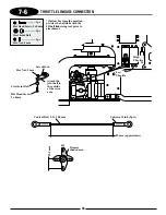
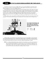
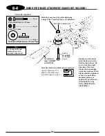
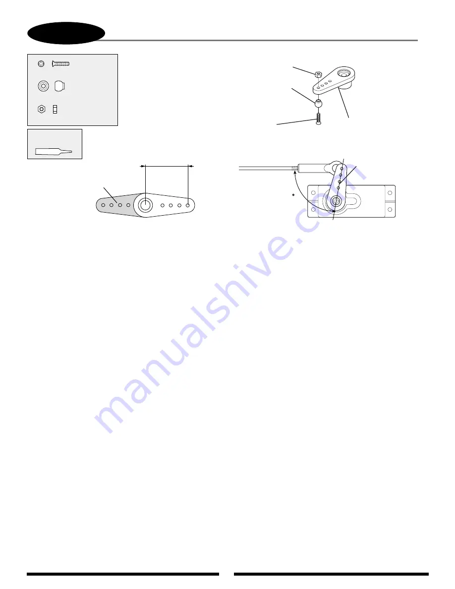
TAIL CONTROL ROD CONNECTION
..............1 pc
Flat Head Screw, 2 x 8 mm
.................1 pc
Steel Joint Ball
.....................1 pc
Hex Nut, 2 mm
Servo Horn
Flat Head Screw,
2 x 8 mm
Steel Joint Ball
Hex Nut, 2 mm
90
18 mm
Use Red
Threadlock
Servo arm should
be offset 1–2 servo
splines at neutral.
Adjust the length of the tail
control rod until the tail
pitch slider is in the center
of its travel and the servo
arm is at the position shown
below (offset).
Note that control
ball is attached
to the inside
of the servo arm.
Remove shaded area.
Offsetting the servo arm as shown
will "balance" the feel of the tail
rotor during flight.
Summary of Contents for Vigor CS
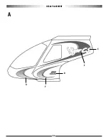
Page 64: ...64 E A C D G F DECAL PLACEMENT ...
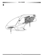
Page 65: ...65 B 3 2 5 1 DECAL PLACEMENT ...


