background image

28

3-5


INSTALLATION OF THE MUFFLER/FUEL LINE CONNECTIONS

Muffler Bolts

.90-Size Muffler

(not included)

(not included)

Pressure Fuel Line Attachment

Fuel Line Connection

Main Fuel Line

(Connect to carburetor)

Fuel Filter

(not included)

Note

: The engine complete with the 

mount, muffler, and clutch can be 

removed and re-installed without 

disassembling for easy service.

Note

: For YS engines with crank 

case pressure please follow 

fuel line plumbing instructions 

provided with your engine.

Summary of Contents for Vibe 90SG

Page 1: ...SG Specifications Overall Length 53 5 in 1359mm Height 17 25 in 438mm Main Rotor Diameter 63 in 1600mm Tail Rotor Diameter 11 34 in 288mm Gear Ratio 8 1 4 65 Weight no fuel 10 25 10 75 lb 4 65 4 88 kg Control System 120 or 140 CCPM ...

Page 2: ...NSTALLATION 15 2 5 TAIL PINION UNIT INSTALLATION 16 2 6 CCPM LEVERS INSTALLATION 17 2 7 FRONT BED INSTALLATION 18 2 8 GYRO TRAY BRACKET ATTACHMENT 19 2 9 TANK FRAME ASSEMBLY 20 2 10 FUEL TANK INSTALLATION 21 2 11 LANDING STRUTS ADAPTER INSTALLATION 22 2 12 LANDING GEAR INSTALLATION 23 3 1 MAIN SHAFT MAIN DRIVE GEAR INSTALLATION 24 3 2 COOLING FAN CLUTCH INSTALLATION 25 3 3 ENGINE INSTALLATION 26 3...

Page 3: ...STMENTS 48 JR 12X PROGRAMMING 49 52 JR X9303 2 4 AND XP9303 PROGRAMMING 53 56 JR 7202 AND SPEKTRUM DX7se AND DX7 PROGRAMMING 57 60 6 1 SERVO INSTALLATION 1 61 6 2 SERVO INSTALLATION 2 62 6 3 SERVO HORN INSTALLATION 63 6 4 CCPM CONTROL ROD ATTACHMENT 64 6 5 CHECKING THE SWASHPLATE FOR LEVEL 65 6 6 TAIL CONTROL LINKAGE ATTACHMENT 66 6 7 THROTTLE LINKAGE ATTACHMENT 67 6 8 GYRO RECEIVER BATTERY INSTAL...

Page 4: ...ited flight performance with the reliability and the durability to handle the most demanding aerobatics your wait is over Once you take the controls of the Vibe 90 SG you ll know your wait was worth it Fully tunable hi cyclic head for extreme cyclic response 120 140 CCPM system Driven tail with bearing supported aluminum shaft Accepts the most popular helicopter engines Robust Sprag autorotation c...

Page 5: ...JR red is the U S equivalent of blue JR green is the equivalent of U S red Great care has been taken in filling the bags with the correct quantity of parts and hardware for each section However occasionally mistakes do happen In the event that you find a parts shortage or are in need of technical assistance please contact your local JR Heli Division parts dealer or contact the Horizon Service Cent...

Page 6: ... DYN2440 8900G Gyro Servo JRPG8900G Fuel Line Plug DUB617 Rubbing Alcohol Nylon Wire Ties ASC7709 Engine 90 size nitro YSE0061 Glow Plug HAN3020 and Muffler Double Sided ServoTape BRP7541 DS8717HV Ultra Speed Cyclic Servo x4 including throttle Grease Items Required to Complete Assembly Spektrum AR7100R Receiver SPMAR7100R JB Weld JBW8265S ...

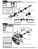
Page 7: ...21 Bevel Gear Pin Bevel Gear T21 long short Bevel Gear T25 Use this Use this in step 1 3 x4 d e R Secure so that the Setscrews are engaged in the D shade recess Tighten the Setscrews 4 x 6mm evenly on all sides of the Tail Drive Joint to ensure no runout Optional Install typical 4mm diameter governor magnet in provided clutch bores with a drop of thin CA Be sure the Setscrew 4x4mm is installed ont...

Page 8: ... x 0 5mm 1pc Front Flat Head Screw 2 x 8mm 8pcs Steel Joint Ball 8pcs T Arm L Elevator Control Arm Flat Head Screw 2 x 8mm 8pcs T Arm Lever 2pcs Steel Joint Ball 8pcs T ARM LEVER ASSEMBLY T Arm R Elevator Arm Setscrew 3 x 6mm 1pc Bevel Gear Pin 1pc BevelGearPin BevelGearT25 Setscrew 3x6mm d e R d e R 2 x d e R x3 d e R x 3 d e R x2 Tail Pinion Gear T22 Poly Slider 0 13mm 1pc Poly Slider 0 13mm for...

Page 9: ...Socket Head Bolt 3 x 8mm 5pcs Tighten the bolts for the main drive gear and the tail drive gear equally to prevent warping Washer 15 x 21 x 0 5mm Socket Head Bolt Main Drive Gear T96 Autorotation Assembly Flat Head Bolt 3 x 6mm 4pcs Tail Drive Gear T86 Tail Drive Gear Hub Autorotation Shaft d e R 5 x Flat Washer 3mm 5pcs Washer 15 x 21 x 0 5mm 1pc Flat Washer 3mm 5pcs 3 x 8mm 5pcs d e R x4 Note Us...

Page 10: ...t included FUEL TANK ASSEMBLY Socket Head Bolt 3 x 25mm 1pc Socket Head Bolt 3 x 25mm TankMetalL FuelTankTube 97mm Cut to a length of 97mm Silicone Tube small 15mm Flat Head Bolt 3 x 6mm 4pcs Socket Head Bolt 3 x 6mm 2pcs Socket Head Bolt 3 x 6mm 2pcs Cross Member with Steps L32P20 3pcs Flat Head Bolt 3 x 6mm 4pcs Cross Member with Steps L32P20 3pcs d e R 2 x d e R x4 Frame Support Plate Note Inst...

Page 11: ...lt 3x6mm 2pcs Socket Head Bolt 3x6mm 2pcs Top Tray Top Tray Frame 2pcs Body Catch 29mm 2pcs Lower Tray Frame 2pcs d e R x2 d e R x2 d e R x2 Flat Head Bolt 3 x 6mm 2pcs Socket Head Bolt 3 x 6mm 2pcs Socket Head Bolt 3 x 8mm 8pcs Socket Head Bolt 3 x 8mm 8pcs Socket Head Bolt 3 x 6mm 2pcs Flat Head Bolt 3 x 6mm 2pcs Note The front radio bed can be installed in the rear position if using a heavy bat...

Page 12: ...pcs Lower Bearing Block with Bearing 12 x 24 x 6mm Cross Member with Steps L32P20 Flat Washer 3mm 2pcs Cross Member 32mm 2pcs Cross Member with Steps 32mm 2pcs Socket Head Bolt 3 x 6mm 2pcs Cross Member with Steps L32P20 1pc Cross Member 32mm 2pcs Cross Member with Steps 32mm 2pcs Top Caution Use care to prevent any adhesive from getting in the race of the bearings Note Note the proper assembly di...

Page 13: ...cs Socket Head Bolt 3 x 14mm 4pcs Cross Member 32mm 1pc Socket Head Bolt 3 x 8mm 2pcs Flat Washer 3mm 8pcs Cross Member 32mm Frame Support Note Install Engine Mount Block and all bolts but do not tighten Once assembled loosely tighten all bolts while pushing the Engine Mount Block toward the front of the frame This disallows any slop in the frame through holes and ensures a correctly aligned Engin...

Page 14: ...ad Bolt 3 x 8mm x8 d e R 2 3 MAIN FRAME ASSEMBLY 3 Socket Head Bolt 3 x 8mm 1pc Button Head Bolt 3 x 5mm 8pcs Button Head Bolt 3 x 5mm 8pcs Rod Guide Nylon Lock Nut 3mm Nylon Lock Nut 3mm 1pc Frame Brace Plate 2pcs ...

Page 15: ... Head Bolt 3 x 8mm Socket Head Bolt 3 x 10mm Socket Head Bolt 3 x 10mm Socket Head Bolt 3 x 12mm Socket Head Bolt 3 x 8mm Flat Washer 3mm 4pcs Socket Head Bolt 3 x 8mm 2pcs Socket Head Bolt 3 x 10mm 3pcs Flat Washer 3mm 4pcs Socket Head Bolt 3 x 12mm 1pc d e R d e R Note Do not tighten the 3 x 10mm and 3 x 12mm bolts completely at this time Note Tighten the 3 x 8mm bolts completely at this time to...

Page 16: ...16 2 5 TAIL PINION UNIT INSTALLATION Socket Head Bolt 3 x 10mm 12pcs Flat Washer 3mm 12pcs Socket Head Bolt 3 x 10mm 12pcs Flat Washer 3mm 12pcs Note Do not tighten bolts completely at this time ...

Page 17: ... 4mm 4pcs T Arm L Elevator Arm 120 CCPM Pivot Pin 2pcs Setscrew 4 x 4mm 4pcs Nylon Lock Nut 4mm 1pc Socket Head Bolt 3 x 30mm 2pcs Lever Spacer 120 CCPM 1pc Lever Spacer 140 CCPM 2pcs 120 CCPM d e R 4 x d e R 4 x Nylon Lock Nut 3mm 2pcs 9 0 T Arm R Fasten with the Nylon LockNut3mmfirst and then fasten with Setscrew 4x4mm for T Arm R Make sure that the elevator control arm is installed so that it i...

Page 18: ...ket Head Bolt 3 x 8mm 6pcs Socket Head Bolt 3 x 10mm 2pcs Nylon Lock Nut 3mm 4pcs Cross Member 32mm 1pc Socket Head Bolt 3 x 10mm 2pcs Socket Head Bolt 3 x 8mm 6pcs Flat Head Bolt 3 x 6mm 2pcs Cross Member 32mm Nylon Lock Nut 3mm 4pcs d e R x2 d e R x 2 d e R 2 x ...

Page 19: ... Body Catch 24mm 2pcs Gyro Tray d e R x2 Self Tapping Screw 3 x 12mm 4pcs Cooling Fan Shroud Bracket Setscrew 3 x 15mm 2pcs Self Tapping Screw 3 x 12mm 4pcs Cooling Fan Shroud Bracket Don t tighten bolts completely at this time 8mm 8mm Flat Washer 3mm 4pcs Flat Washer 3mm 4pcs Flat Washer 3mm 8pcs Don t tighten the cooling fan shroud bracket screws completely at this time ...

Page 20: ...x 8mm 2pcs d e R x2 8mm Hex Hole 2 sets d e R x2 Setscrew 3 x 15mm 2pcs Cross Member 17mm Black 2pcs d e R x4 Cross Member 17mm Black 4pcs Fuel Tank Holder 4pcs Button Head Bolt 3 x 6mm 4pcs Button Head Bolt 3 x 8mm 4pcs Spacer 3mm 4pcs Lock Washer 3mm 4pcs Cross Member 17mm Black 2pcs Socket Head Bolt 3 x 8mm 2pcs Cross Member 32mm d e R 2 x For YS Engine use only Tank Frame 2pcs Note For YS Engi...

Page 21: ...21 Socket Head Bolt 3 x 8mm 4pcs 2 10 FUEL TANK INSTALLATION Socket Head Bolt 3 x 8mm 4pcs Silicone Tube Grommet SiliconeTubeGrommet 1pc d e R 4 x Pass silicone tube through this hole ...

Page 22: ...ad Bolt 3 x 10mm 2pcs Socket Head Bolt 3 x 28mm 4pcs Nylon Lock Nut 3mm 2pcs Flat Washer 3mm 4pcs Spacer 13mm 4pcs Socket Head Bolt 3 x 10mm 2pcs Socket Head Bolt 3 x 12mm 2pcs Socket Head Bolt 3 x 28mm 4pcs Flat Washer 3mm 4pcs Nylon Lock Nut 3mm 2pcs Spacer 13mm 4pcs Frame Lower Bracket 2pcs d e R 4 x 2 x d e R ...

Page 23: ...Nut 3mm 4pcs Setscrew 4 x 4mm 4pcs Socket Head Bolt 3 x 20mm 4pcs Socket Head Bolt 3 x 20mm 4pcs Flat Washer 3mm 8pcs Landing Strut 2pcs Socket Head Bolt 3 x 8mm 6pcs Nylon Lock Nut 3mm 4pcs d e R x 6 Optional Note The ends of the landing skid can be trimmed up to 11 2 in 38 5mm as desired to shorten them for looks Use caution not to cut the skids too short measure prior to cutting to verify prope...

Page 24: ...mm 1pc Setscrew 4 x 4mm 1pc Socket Head Bolt 3 x 10mm 1pc Short Long Nylon Lock Nut 4mm d e R d e R When fastening the Main Rotor Shaft Collar pull it up against the top bearing block and push down on the Main Rotor Shaft and fasten with the Socket Head Bolt 3 x 10mm first Then fasten with Setscrew 4 x 4mm Make sure the Main Rotor Shaft is secure Note Tighten main shaft collar setscrew after clamp...

Page 25: ...at Head Screw 2 x 8mm 1pc Steel Joint Ball 1pc Button Head Bolt 3 x 6mm 4pcs Hex Nut 2mm 1pc Tapered Collet Upper 1pc Tapered Collet Lower 1pc d e R Socket Head Bolt 4 x 8mm 2pcs Flat Washer 3mm 4pcs Socket Head Bolt 4 x 15mm 4pcs Flat Washer 4mm 4pcs Engine Mount Socket Head Bolt 4 x 15mm 4pcs Flat Washer 4mm 4pcs Flat Washer 3mm 4pcs Top Short Long d e R 2 x Note When securing the engine bolts 4...

Page 26: ...there is no gear backlash with the paper in place and then tighten the bearing block screws Then remove the paper and note that there should be a very slight amount of backlash in the gears The mesh plates and preset engine alignment will allow only very small movement of the pinion gear and make setting this mesh relatively easy Repeat this procedure for setting the tail drive gear mesh Check the...

Page 27: ...ered around the fan Tighten the fan mounts then attach the right half of the shroud With some engines and Ni starters you may need to trim the glow plug opening in the shroud for additional clearance Self Tapping Screw 3 x 12mm 4pcs Self Tapping Screw 2 6 x 8mm 6pcs Self Tapping Screw 3 x 12mm 4pcs Self Tapping Screw 2 6 x 8mm 6pcs Cooling Fan Shroud Right Cooling Fan Shroud Left Glow Plug Opening...

Page 28: ...achment Fuel Line Connection Main Fuel Line Connect to carburetor Fuel Filter not included Note The engine complete with the mount muffler and clutch can be removed and re installed without disassembling for easy service Note For YS engines with crank case pressure please follow fuel line plumbing instructions provided with your engine ...

Page 29: ...he ball links with the JR Ball Link Sizing tool prior to attachment 4 1 SWASHPLATE WASHOUT INSTALLATION Socket Head Bolt 3 x 14mm 2pcs Washer 3 x 4 5 x 1mm 2pcs Setscrew 3 x 3mm 3pcs Joint Ball Spacer 2 75mm 4pcs Flat Head Screw 2 x 10mm 6pcs Control Ball 9mm 3pcs Steel Joint Ball 6pcs Long Control Ball 28 25mm 2pcs 3 x d e R Hold Upper Plate and check play Assembly 2pcs This Position As shown in ...

Page 30: ...Washer 3 x 4 5 x 1mm 2pcs The position of Joint Ball Socket Head Bolt 3 x 6mm 2pcs Note the proper direction of the Mixing Arm Steel Joint Ball 4pcs Flat Head Screw 2 x 8mm 4pcs Pitch Arm 2pcs Mixing Arm 2pcs Washer 3 x 4 5 x 1mm 2pcs Main Blade Holder 2pcs d e R 2 x d e R 4 x d e R 2 x Optional Note For increased cyclic response move the steel joint ball mounting positions as shown ...

Page 31: ... the spindle bolts down does not cause a notchy bearing feel in the grips Remove the steel shim washer or use thinner steel shim washers if required Damper Rubber 90 2pcs DamperRubber 90 2pcs for adjustment Large I D Apply Grease Small I D Nylon Lock Nut 5mm 2pcs Main Blade Holder Rotor Spacer 4pcs Socket Head Bolt 5 x 10mm 2pcs Thrust Bearing 9 x 17 x 5mm 2pcs Spindle Shaft Washer 2pcs Long Shank...

Page 32: ... 4mm 2pcs Seesaw Spacer Collar 2pcs Note the proper direction of the Seesaw Shaft 214 5mm 214 5mm Button Head Bolt 4 x 8mm 2pcs Button Head Bolt 4 x 8mm 2pcs Setscrew 4 x 4mm 2pcs Flybar 520mm x2 Red R e d x 4 The universal links should attached to the Ball Joint are to the outside be adjusted so that when the words JR PROPO Threaded Rod 2 3 x 30mm 2pcs Universal Ball Link 4pcs 14 5mm 2 sets ...

Page 33: ...h standard bolts This increases the chances of failures in flight Be sure to engage the rotor head pins 2 into the washout base driver before securing the rotor head assembly in place Align the flybar paddles to be even with each other and the flybar cage 4 5 ROTOR HEAD INSTALLATION Control Ball 4mm 2pcs Special Socket Head Bolt 4 x 26mm 1pc Socket Head Bolt 3 x 8mm 2pc Nylon Lock Nut 4mm 1pc d e ...

Page 34: ...SHPLATE 2pcs Threaded Rod 2 3 x 80mm Universal Ball Link short Universal Ball Link Universal Ball Link 64 5mm 3 5mm 17 5mm The universal links short have gaps Install these links so this side faces The universal links should attached to the Ball Joint are to the outside at the edge on one side only the Ball Joint be adjusted so that when the words JR PROPO Tip The JR Ball Links are designed with l...

Page 35: ... Bearing 8 x 14 x 4mm 2pcs Oil Apply oil to the inside of the Tail Boom then install the Shaft Drive Guide Attach the bearing first n e e r G x2 250mm Do not apply threadlock to the inside of the ball bearings Button Head Bolt 3 x 4mm 4pcs Drive Shaft Insert 2pcs Drive Shaft Pin 2pcs Button Head Bolt 3 x 4mm 4pcs Drive Shaft Collar 2pcs Drive Shaft Pin 2pcs 4 x d e R Red x2 Note Install tail boom ...

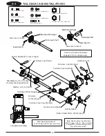
Page 36: ... Pitch Base Note the proper direction of Tail Pitch Base and Tail Gear Case Plate Setscrew 3 x 6mm Tail Output Shaft BevelGearShaft BevelGearPin Setscrew 3 x 6mm BevelGearT22Input BevelGearT22Output BevelGearPin Secure so that the Setscrews engage in the D shape recess Setscrew 4 x 4mm 2pcs Setscrew 3 x 6mm 2pcs Setscrew 4 x 6mm 4pcs Bevel Gear Pin 2pcs Setscrew 4 x 6mm 4pcs 4 x d e R d e R x4 x2 ...

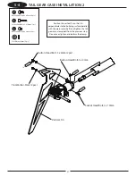
Page 37: ... step 5 4 TAIL GEAR CASE INSTALLATION 2 Button Head Bolt 3 x 6mm 2pcs Flat Washer 3mm 2pcs Button Head Bolt 3 x 4mm 1pc Socket Head Bolt 3 x 10mm 1pc Button Head Bolt 3 x 4mm Socket Head Bolt 3 x 10mm d e R d e R 2 x d e R Position the vertical fin so that it is perpendicular to the building surface parallel with the main rotor shaft and tighten the tail gear case clamp bolt from the previous step...

Page 38: ...talling 5 5 TAIL PITCH CONTROL LEVER INSTALLATION Button Head Bolt 3 x 8mm 2pcs Tail Pitch Slider Bolt 2pcs Tail Pitch Base Bearing Collar 2pcs CA Stopper Ring 2mm 4pcs Tail Pitch Link Pin 2pcs Steel Joint Ball 1pc Flat Head Screw 2 x 8mm 1pc Tail Pitch Link 2pcs Note the proper direction The side with four circle marks of the Tail Pitch Link is toward the direction of the arrow Tail Pitch Slider ...

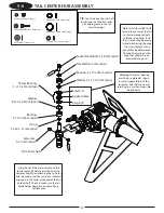
Page 39: ...y without play TIP Use thin oil on the tail shaft to lubricate the tail pitch slider Also apply grease to the tail thrust bearings 5 6 TAIL CENTER HUB ASSEMBLY Setscrew 4 x 4mm 2pcs Washer 5 x 7 x 0 5mm 2pcs Washer 8 x 10 x 0 5mm 2pcs Flat Washer 3mm 2pcs O ring 3 5 x 5 5 x 1mm 2pcs Apply Grease Socket Head Bolt 3 x 8mm 2pc d e R 2 x Warning The thrust bearing must be assembled as shown or catastr...

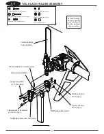
Page 40: ...s Nylon Lock Nut 2mm 8pcs Nylon Lock Nut 3mm 2pcs Socket Head Bolt 2 x 10mm 8pcs Rotation direction Be sure to note the correct direction of the tail rotor blades during assembly 5 7 TAIL BLADE HOLDER ASSEMBLY Socket Head Bolt 2 x 10mm 8pcs Nylon Lock Nut 2mm 8pcs Special Socket Head Bolt 3 x 15mm 2pcs Nylon Lock Nut 3mm 2pcs Flat Head Bolt 2 x 10mm 2pcs Steel Joint Ball 2pcs ...

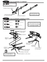
Page 41: ...and tighten the two Tail Support Clamp Bolts 5 8 TAIL BOOM BRACE ASSEMBLY 5 9 TAIL BOOM BRACE INSTALLATION Socket Head Bolt 2 6 x 12mm 4pcs Socket Head Bolt 3 x 12mm 2pcs Nylon Lock Nut 3mm 2pcs Flat Washer 3mm 4pcs Note the proper direction of the Tail Brace Connectors Note the proper direction of the Lower Tail Support Clamp d e R 2 x Socket Head Bolt 3 x 8mm 2pcs Socket Head Bolt 3 x 10mm 2pcs ...

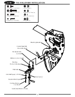
Page 42: ...t 3 x 16mm Steel Joint Ball 2pcs Bellcrank d e R d e R 2 x 5 10 TAIL BELLCRANK INSTALLATION Socket Head Bolt 2 6 x 6mm 2pcs Flat Head Screw 2 x 10mm 1pc Socket Head Bolt 3 x 16mm 1pc Steel Joint Ball 2pcs Brass Spacer 1pc Washer 3 x 4 5 x 0 4mm 1pc Joint Ball Spacer 2 75mm 1pc Flat Head Screw 2 x 12mm 1pc Flat Head Screw 2 x 10mm Joint Ball Spacer 2 75mm ...

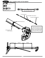
Page 43: ... 3pcs 5 11 TAIL CONTROL ROD ATTACHMENT Self Tapping Screw 2 x 8mm 3pcs Tail Rod Collar Guide B 3pcs Universal Ball Link 2pcs 140mm 220mm 240mm Note Sight down from the tail box down the length of the boom and set the tail rod guides to align vertically Adjust the Guide Collars up down as needed for smooth operation of the tail rod assembly ...

Page 44: ... operate with the appropriate control stick 3 Reset the throttle stick to the center position making sure the throttle trim is still at low 4 Turn off the receiver switch first followed by the transmitter For proper operation it s important that the servo horns are positioned on the servos in the exact neutral position Although most computer radio systems offer a sub trim feature it is suggested t...

Page 45: ...ashplate left and right If an elevator pitch input is given all three servos work together to move the swashplate fore and aft For collective it s also the strength of three servos that will move the swashplate up and down the main rotor shaft With two or three servos working at the same time during any given control input servo torque is maximized and servo centering is also increased In addition...

Page 46: ... servos must move to tilt the swashplate fore and aft but their directions vary The servos move together in the same direction while the rear swashplate servo moves in the opposite direction For example when a down elevator forward cyclic command is given the front swashplate servos will move the swashplate down while the rear swashplate servo moves so that the swashplate will tilt forward During ...

Page 47: ...e event that a control surface is working in the wrong direction the control function can only be reversed by changing the desired CCPM value for that function from a to a value or vice versa Example If when you increase the collective pitch the pitch of the main blades actually decreases it will be necessary to access the CCPM function and change the travel value for this function from to or to T...

Page 48: ...as older 10 series systems are equipped with 120 and or 140 CCPM electronics for use with JR CCPM machines Radios you may be flying now like the X347 X388S XP783 and XP8103 have 120 CCPM capability built in but require activation by the Horizon Service Department Please call 877 504 0233 for details Please note that many XP8103 systems have the CCPM function already activated Please check with the...

Page 49: ...t move the cursor to the MODEL SEL function Press the roll selector to enter the model select function Select the desired model number to be used then press the roll selector Next move the roll selector to highlight LST and press the roll selector Move the roll selector to highlight MDL RESET then press the roll selector Press the CLEAR key then press YES to reset the data of the current model sel...

Page 50: ...t the desired CCPM type 120 or 140 Move the roll selector to highlight LST and press the roll selector to exit the system mode D D R and EXPO Selection Turn the power switch on then press the ENT key to enter function mode Move the roll selector to highlight the D R and EXPO function then press the roll selector to enter the function Set the Dual Rate and Expo values as desired below are suggested...

Page 51: ...nter the function Adjust the values as shown by moving the roll selector to highlight the desired channel while using the control stick to select up down or left right values to be adjusted Please note that the required travel values will vary based on the type of servo selected Press the LST key to return to the menu G CCPM Settings Move the roll selector to highlight the SWASH MIX function then ...

Page 52: ...on Move the roll selector to highlight the GYRO function then press the roll selector to enter the function Set the gyro gain as shown as a starting point for the G770 3D gyro Adjust the percentage as necessary when flying the heli Other gyros may require different settings consult your gyro manual for further information on setting the gain Press the LST key to return to the menu J Governor Move ...

Page 53: ...ext move the cursor to the MODEL SEL function Press the roll selector to enter the model select function Select the desired model number to be used then press the roll selector Next move the roll selector to highlight LST and press the roll selector Move the roll selector to highlight MDL RESET then press the roll selector Press the CLEAR key then press YES to reset the data of the current model s...

Page 54: ...t the desired CCPM type 120 or 140 Move the roll selector to highlight LST and press the roll selector to exit the system mode D D R and EXPO Selection Turn the power switch on then press the ENT key to enter function mode Move the roll selector to highlight the D R and EXPO function then press the roll selector to enter the function Set the Dual Rate and Expo values as desired below are suggested...

Page 55: ...to enter the function Adjust the values as shown by moving the roll selector to highlight the desired channel while using the control stick to select up down or left right values to be adjusted Please note that the required travel values will vary based on the type of servo selected Press the LST key to return to the menu G CCPM Settings Move the roll selector to highlight the SWASH MIX function t...

Page 56: ...return to the menu I Gyro Sensitivity Selection Move the roll selector to highlight the GYRO function then press the roll selector to enter the function Set the gyro gain as shown as a starting point for the G770 3D gyro Adjust the percentage as necessary when flying the heli Other gyros may require different settings consult your gyro manual for further information on setting the gain Press the L...

Page 57: ...t will be necessary to select the desired model number to be used A Model Select Data Reset Press the Down and Select keys while turning the power switch on to enter the system mode Next move the cursor to the MODEL SEL function with the UP key Select the desired model number to be used with the increase or decrease key Next press the UP key until MODEL RESET is displayed Press the CLEAR key then ...

Page 58: ...R to AUX2 Press the down and select keys together to exit the system menu D D R and EXPO Selection Turn the power switch on then press the DOWN and SELECT keys together to enter the function mode Press the UP key to select the D R and EXPO function Set the Dual Rate and Expo values as desired below are suggested settings ...

Page 59: ...ettings while using the control stick to select up down or left right values to be adjusted Please note that the required travel values will vary based on the type of servo selected Use the gear travel adjust values to set the governor setting to adjust the head speed of the heli as desired G CCPM Settings Press the UP key to select the SWASH MIX function Change the value of the aileron elevator a...

Page 60: ...tch is pulled the throttle servo does not move with the throttle stick at idle and throttle trim set at the idle position I Gyro Sensitivity Selection Press the UP key to select the GYRO SENS function Set the gyro gain as shown as a starting point for the G770 3D gyro Adjust the percentage as necessary when flying the heli Other gyros may require different settings consult your gyro manual for fur...

Page 61: ... Plate 4pcs We recommend the same model be used for all Swashplate servos Be careful when tightening the tapping bolt If it is too loose the servo will move Over tightening it will cause damage The ideal position will dent the rubber slightly Be sure to note the fore and aft position of the servo output shaft Screw Supplied with Switch Switch Dampener 2pcs Switch Harness Switch Dampener 2pcs 120 C...

Page 62: ...o Pitch Servo Ch 6 Flat Washer 2 6mm 12pcs Self Tapping Screw 2 6 x 12mm 12pcs 6 2 SERVO INSTALLATION 2 Self Tapping Screw 2 6 x 12mm 12pcs Flat Washer 2 6mm 12pcs Type B Servo Mounting Plate 6pcs Elevator Servo Ch 3 Pitch Servo Ch 6 140 CCPM 120 CCPM ...

Page 63: ...w 2 x 8mm 6pcs Hex Nut 2mm 6pcs 2pcs 27mm d e R 6 x 6 3 SERVO HORN INSTALLATION Flat Head Screw 2 x 8mm 6pcs Steel Joint Ball 6pcs Hex Nut 2mm 6pcs 1pc JR Large HD Servo Horn 3pcs Note See Step 6 5 to properly center the wheels on the servos ...

Page 64: ...A B C Threaded Rod 2 3 x 85mm 2pcs Threaded Rod 2 3 x 100mm 2pcs Special Threaded Rod 2 5 x 165mm 2pcs Universal Ball Link 12pcs 2pcs 2pcs 2pcs 84mm 142mm The rod lengths are given as a guide only They will require fine adjustment later B A C ...

Page 65: ...pitch in later steps 6 5 CHECKING THE SWASHPLATE FOR LEVEL 90 90 90 90 90 90 90 90 90 90 90 90 After the control linkages have been attached to the swashplate it will be necessary to check the swashplate to ensure that it is level To do this turn on the radio system and place the collective stick in the center position as before Next check to make sure that all trim levers and knobs are also in th...

Page 66: ...TROL LINKAGE ATTACHMENT Flat Head Screw 2 x 10mm 1pc Steel Joint Ball 1pc Hex Nut 2mm 1pc Super Horn 2 x 10mm Remove shaded area Universal Ball Link 2pcs Threaded Rod 2 3 x 250mm 230mm approximate Rod Guide Collar Rod Guide Collar 1pc Adjust ball position to suit gyro if needed ...

Page 67: ...nt Ball 1pc Hex Nut 2mm 1pc Remove shaded area Universal Ball Link 2pcs Threaded Rod 2 3 x 100mm 82mm approximate Flat Head Screw 2 x 8mm m m 5 2 1 d e R Flat Head Screw 2 x 8mm 1pc Servo Horn 1 2 Stick Throttle Position Throttle Barrel 1 2 open 90 90 Hex Nut 2mm ...

Page 68: ...c Also make sure that the front radio bed is free from oil and debris Clean with rubbing alcohol to ensure proper adhesion Double sided servo tape and sponge foam rubber are not included in this kit Use the hook and loop straps included in this kit to secure Be certain when installing the gyro unit to the front radio bed that it does not come in contact with the frame of the HookandLoopStrapL Remo...

Page 69: ...tal servos are used the adjustment required is generally very small if any These variations in travel can be corrected by altering the travel value of each servo slightly through the travel adjustment function To check the pitch to aileron mixing it will first be necessary to position the collective stick in the center position and make sure the swashplate is level Next move the collective stick f...

Page 70: ... is found proceed to the next step In our example we have shown that the swashplate has tilted backward as the collective has been increased to full high pitch This would indicate that the top servo s maximum travel is less than that of the two left right servos In this condition we suggest that the travel value for the rear servo be increased slightly 5 10 Repeat the above procedure and decrease ...

Page 71: ...range that you will require will be 24 total The maximum pitch range mentioned above must be established through the use of the pitch travel value in the CCPM function As mentioned previously do not try to establish the maximum pitch curve values through adjustment of the travel adjustment function as this will alter the pitch to aileron and pitch to elevator travel values established earlier Plea...

Page 72: ...everse the gyro and re test Generally with the G770 3D Gyro it will be necessary to reverse the direction of the gyro with the switch on the gyro Governor Setting Set the Governor settings as shown in the radio programming section Set the throttle curve in normal mode as shown then set the throttle curves in stunt 1 and 2 up to be a straight line at the top of the graph 100 and adjust the governor...

Page 73: ...m 2pcs Rubber Grommets 4pcs Check to ensure the body does not come in contact with any portion of the main frame muffler linkages etc Trim for clearance if necessary Blade Holder Main Rotor Blade Bolt hole 5mm 12mm thick grips Length 680 720mm not included Screw the Long Shank Bolt into the nylon grips at the tip of the Lock Nut The Main Blades should be tightened so they can pivot when moderate p...

Page 74: ...properly and in the correct direction Blade Tracking Adjustment Blade tracking is an adjustment to the main rotor blade pitch that must be accomplished during the initial test flights Although the blade pitch angle in each blade may appear equal it is still possible for a set of main rotor blades to run out of track making adjustment necessary Main rotor blades that are out of track with one anoth...

Page 75: ...sary to re static balance the main rotor blades A Use two different blade tracking tape colors e g black and red at the tip of each main rotor blade Caution Be sure to maintain a safe distance from the helicopter 15 to 20 feet 4 7 to 6 meters when tracking main rotor blades Blade Labeling for Tracking Purposes Out of Track Incorrect Adjustment is necessary Red Black Red Red In Track Correct Adjust...

Page 76: ...on and reduce wear Inspect the washout base every 50 75 flights If excessive wear is noted replace as needed Tail Pitch Slider Lubricate the tail pitch slider using light oil every 5 10 flights to ensure smooth operation and reduce wear Check Ball Link Wear Check to ensure that all universal links fit freely but securely to the control balls If there is excessive play noted adjust and or replace t...

Page 77: ...77 ...

Page 78: ...ACEMENT PARTS LISTING 970001 980031 980037 970104 980037 980037 980031 970001 980032 970002 996243 980015 960072 980036 970004 996245 996334 980106 980056 980043 996317 980106 970004 970004 970025 996340 996244 961303 961300 961259 ...

Page 79: ...80015 SOCKET HEAD BOLTS 3x12mm 10 980036 PLATE WASHERS 3mm 10 960072 RUBBER GROMMET 4 996243 FRP BODY SET VIBE 90SG 1 961259 HOOK AND LOOP STRAP L 2 961303 HOOK AND LOOP STRAP S 2 961300 BLADE HOLDER 1 970025 SWITCH DAMPER RUBBER 4 996245 LINKAGE SET CCPM 1 996334 ELEVATOR CONTROL ROD 2 5x165mm 1 980106 CONTROL ROD 2 3x100mm 2 980056 CONTROL ROD 2 3x85mm 2 980043 CONTROL ROD 2 3x35mm 2 970004 UNIV...

Page 80: ...970001 970576 970576 981032 996247 996248 980012 980015 996250 996251 981023 981023 970442 981024 996249 996253 996254 980074 970093 996255 980013 996257 981052 980201 980164 980181 996256 970533 970069 970004 970098 996246 980105 980042 980052 996344 ...

Page 81: ...LDER 2 980074 SOCKET HEAD BOLTS 5x10mm 10 996254 SPINDLE SHAFT TUBE 1 996253 BLADE SPINDLE SHAFT 1 970093 SPINDLE SHAFT WASHER 2 980105 CONTROL ROD 2 3x80mm 2 980042 CONTROL ROD 2 3x30mm 2 980052 CONTROL ROD 2 3x15mm 2 996246 LINKAGE SET ROTOR HEAD 1 970098 UNIVERSAL BALL LINK SHORT 5 970004 UNIVERSAL BALL LINK ALL 10 980201 BUTTON HEAD BOLTS 4x8mm 10 981052 BEARING SEALED 5x9x3mm 2 996257 SEESAW ...

Page 82: ...PARTS LISTING 996258 980032 970002 970576 981031 981031 970119 980059 996149 970566 981015 996260 996152 970184 980067 970078 980032 970002 970184 996148 996261 981021 996262 996264 996263 960979 980004 980131 983080 ...

Page 83: ... STOPPER RING 2mm 10 980059 SOCKET HEAD BOLTS 3x14mm 10 970119 SPACER 3x5x1 8mm 2 996260 120 140 ALUMINUM SWASHPLATE 1 970184 BALL ARM 9mm 1 970078 CONTROL BALL SPACER 2 75mm 2 980067 SETSCREWS 3x3mm 10 996152 LONG CONTROL BALL 1 981021 BEARING SEALED 4x8x3mm 2 996261 SEESAW SHAFT w BEARING 1 996262 BALL ARM L4C 4mm 2 996263 FLYBAR ARM A 2 996264 FLYBAR ARM A B SET 1 960979 FLYBAR ARM B 2 980004 S...

Page 84: ...70457 980036 980012 980059 980014 980013 996267 970496 996268 970496 970457 996265 996275 996272 981032 980039 980031 970001 996273 980039 980031 970001 996272 981032 980021 980031 970001 980004 994018 980004 996271 980164 996270 970209 980187 980013 981036 970004 996269 996336 981059 ...

Page 85: ...SS MEMBER w STEPS 32mm 2 996265 MAIN FRAME LEFT w BEARING 1 994018 ELEVATOR CONTROL ARM 1 980004 SETSCREWS 4x4mm 10 980031 FLAT HEAD SCREWS 2x8mm 10 970001 JOINT BALLS 2x8mm SCREWS 10 970004 UNIVERSAL BALL LINK ALL 10 996269 ELEVATOR A ARM 1 981036 BEARING SEALED F4x8x3mm 2 980187 SOCKET HEAD BOLTS 2 3x15mm 5 970209 CCPM A ARM COLLAR 2 980164 NYLON LOCK NUT 4mm t3 8 10 996270 ELEVATOR A ARM BASE 1...

Page 86: ...86 REPLACEMENT PARTS LISTING 996277 970020 980013 980059 980036 996276 980013 980014 960293 980024 980013 980039 996278 980030 996279 980065 980012 980036 980013 996283 980012 ...

Page 87: ...RAME BRACE PLATE 1 980030 BUTTON HEAD BOLTS 3x5mm 10 996277 FRAME SUPPORT 1 970020 CROSS MEMBER 32mm 2 980059 SOCKET HEAD BOLTS 3x14mm 10 980036 PLATE WASHERS 3mm 10 980014 SOCKET HEAD BOLTS 3x10mm 10 996276 ENGIN MOUNT BLOCK 1 996279 FRAME SUPPORT PLATE 1 980065 FLAT HEAD BOLTS 3x6mm 10 980012 SOCKET HEAD BOLTS 3x6mm 10 996283 CROSS MEMBER w STEPS L32P20 2 ENGINE MOUNT BLOCK ...

Page 88: ...ISTING 980013 980012 996281 996280 980065 996172 996283 980039 980013 961329 980013 980039 970457 996282 996284 996285 980068 996002 980036 980029 980013 961187 996002 980036 980029 960924 960040 961292 960096 980061 970034 ...

Page 89: ...AT HEAD BOLTS 3x6mm 10 996280 TOP TRAY 1 996283 CROSS MEMBER w STEPS L32P20 2 996172 FRONT BED MOUNT 3 980068 SETSCREWS 3x15mm 10 996285 BODY CATCH 24mm 2 980029 SELF TAPPING SCREWS 3x12mm 10 980036 PLATE WASHERS 3mm 10 996002 COOLING SHROUD BRACKETS 2 961187 GYRO MOUNT 1 961292 SILICONE FUEL TUBE 2 5x3 6x150 1 960040 SILICONE FUEL TUBE 2 5x5x1000 1 960924 FUEL TANK SET 600cc 1 970034 FUEL TANK HO...

Page 90: ...960923 970050 996287 996003 980036 980091 970102 980037 980031 970001 980071 980064 996289 980036 980061 996288 996290 980071 980203 996006 980026 980036 980029 980013 996286 970458 980068 980013 980091 980119 980072 970224 980039 980014 980036 ...

Page 91: ...ON LOCK NUT 3mm t2 8 10 980091 BUTTON HEAD BOLTS 3x6mm 10 980119 BUTTON HEAD BOLTS 3x8mm 10 980090 SOCKET HEAD BOLTS 4x8mm 10 981057 ONE WAY BEARING 8x12x12mm 1 960923 CLUTCH ASSEMBLY 1 970050 TAPER COLLET UB 1 980203 SOCKET HEAD BOLTS 4x20mm 10 980071 PLATE WASHERS 4mm 10 996290 MOUNT BLOCK SPACER T96 1 996289 SPACER 3x10x14mm 2 996288 ENGINE MOUNT 1 980061 SOCKET HEAD BOLTS 3x25mm 10 980031 FLAT...

Page 92: ...291 996292 980004 980014 996294 996293 96295 980036 980013 996296 980065 970578 980181 980164 996297 996299 996335 981037 970451 996298 981056 981056 996301 996302 996300 981073 980004 960927 980014 980015 980036 996175 980014 996345 ...

Page 93: ...TS 3x8mm 10 980036 PLATE WASHERS 3mm 10 996295 MAIN DRIVE GEAR T96 1 980014 SOCKET HEAD BOLTS 3x10mm 10 980004 SETSCREWS 4x4mm 10 980015 SOCKET HEAD BOLTS 3x12mm 10 960927 STARTER HEX ADAPTER 1 981073 BEARING SEALED 6x13x5mm 2 996300 START SHAFT TOP BEARING BLOCK 1 981056 BEARING SEALED 12x21x5mm 1 996301 START SHAFT BEARING BLOCK 1 996298 PINION GEAR T12 1 996335 CLUTCH BELL ASSEMBLY 1 996345 SWA...

Page 94: ...CEMENT PARTS LISTING 996306 981004 970577 996304 980168 996308 996309 996310 981004 980004 996311 970570 980129 980115 980022 980014 980036 960094 980069 996307 981004 981068 996305 996303 980168 996304 980051 ...

Page 95: ...EAD BOLTS 3x40mm 10 980014 SOCKET HEAD BOLTS 3x10mm 10 980036 PLATE WASHERS 3mm 10 980004 SETSCREWS 4x4mm 10 996310 TAIL PINION GEAR T22 1 996309 TAIL PINION SHAFT 1 970570 CROSS MEMBER 28mm 2 996311 TAIL PINION UNIT CASE LFT RT 1 970577 WASHER 5x7x0 5mm 2 980051 POLY SLIDER t0 13 10 960094 TAIL DRIVE JOINT 1 980069 SETSCREWS 4x6mm 10 996307 TAIL PINION UNIT BEARING CASE B 1 981068 BEARING SEALED ...

Page 96: ...96 REPLACEMENT PARTS LISTING 980020 996313 996312 980036 980039 996005 980014 980039 996314 980013 961000 980004 980060 980036 970048 960119 996315 960733 980022 980039 996316 970004 ...

Page 97: ...LL LINK ALL 10 980014 SOCKET HEAD BOLTS 3x10mm 10 996005 LANDING STRUT MOUNT 4 996312 FRAME LOWER BRACKET 1 980036 PLATE WASHERS 3mm 10 996313 SPACER 3x8x13mm 2 980020 SOCKET HEAD BOLTS 3x28mm 10 980060 SOCKET HEAD BOLTS 3x20mm 10 980004 SETSCREWS 4x4mm 10 961000 LOW PROFILE LANDING STRUT 2 960119 LANDING SKIDS 2 970048 LANDING SKID CAP 4 980013 SOCKET HEAD BOLTS 3x8mm 10 996314 BOTTOM FRAME PLATE...

Page 98: ...980069 996328 981004 981068 980204 980014 996305 996304 996322 980168 996324 996304 980168 996325 996323 996327 980205 981073 980091 996326 980004 981073 996329 980119 970150 996320 996198 981067 980168 980204 996319 970288 980009 996318 996337 996338 994023 ...

Page 99: ...AD BOLTS 3x10mm 10 996328 TAIL GEAR CASE ASSEMBLY 1 981068 BEARING SEALED 12x18x4mm 1 996305 BEVEL GEAR SHAFT 1 996304 BEVEL GEAR PIN 2 996322 BEVEL GEAR T22 INPUT 1 970150 O RING 5x7x1mm 2 996329 TAIL PITCH BASE 1 996338 TAIL GEAR CASE PLATE RIGHT w BEARING 1 994023 WASHER 6x10x0 5mm 2 996337 TAIL DRIVE SHAFT SET 1 980119 BUTTON HEAD BOLTS 3x8mm 10 981073 BEARING SEALED 6x13x5mm 2 996326 TAIL OUT...

Page 100: ... 981028 980039 980128 996332 980131 980032 970002 996331 980004 970163 961206 960056 961261 981015 961201 981065 996330 980119 970530 961202 970529 981038 980031 970001 980015 980013 980036 960132 996321 980030 996159 980117 970082 980032 970002 960265 970121 981031 970078 980135 980017 ...

Page 101: ... SEALED F4x7x2 5mm 2 970529 TAIL PC BEARING COLLAR 2 996330 TAIL SLIDE RING SLEEVE 1 981065 BEARING SEALED 7x11x3mm 2 961201 TAIL SLIDE RING 1 961206 TAIL PITCH PLATE SET 1 960056 TAIL PITCH LINK 2 981015 CA STOPPER RING 2mm 10 961261 TAIL PITCH PLATE 1 980004 SETSCREWS 4x4mm 10 970163 TAIL HUB O RING 3 5x5 5x1mm 2 996331 TAIL CENTER HUB 1 960265 MIXING LEVER w BEARING 1 970082 WASHER 3x4 5x0 4mm ...

Page 102: ...tely and do not resume flight until the cause of the problem has been ascertained and corrected Safety can never be taken lightly Do not fly near power lines Warranty Information Warranty Period Horizon Hobby Inc Horizon warranties that the Products purchased the Product will be free from defects in materials and workmanship at the date of purchase by the Purchaser Limited Warranty a This warranty...

Page 103: ...epaired please call for a Return Merchandise Authorization RMA Pack the Product securely using a shipping carton Please note that original boxes may be included but are not designed to withstand the rigors of shipping without additional protection Ship via a carrier that provides tracking and insurance for lost or damaged parcels as Horizon is not responsible for merchandise until it arrives and i...

Page 104: ...pped to the following address Horizon Service Center 4105 Fieldstone Road Champaign Illinois 61822 USA Please call 1 877 504 0233 or visit horizonhobby com to find our distributor for your country for support with any questions or concerns regarding this product or warranty ...

Page 105: ...105 ...

Page 106: ...14571 Printed 12 08 2009 Horizon Hobby Inc 4105 Fieldstone Road Champaign Illinois 61822 877 504 0233 horizonhobby com ...

Reviews: