6
INSTALLATION WIRING
Typical wiring diagrams are shown on pages 7-8.
Actual wiring should follow the print supplied with
the actuator
.
The wiring diagram shows the fundamental connec-
tions for the standard three-wire reversible single-
phase motor, and the standard permanent magnet dc
motor. These units show an arrangement with torque
switches, four limit switches, two feedback potentiom-
eters, and a heater. To meet special requirements,
certain items shown may not be supplied.
In all
instances the wiring diagram appropriate to the
equipment will be supplied with each unit
.
A barrier type terminal strip is located under the rear
cover opposite the output shaft. Two conduit entries
are located in the side of the unit to accommodate
standard 1 inch N.P.T. and inch N.P.T. fittings.
CAUTION: On standard single-phase wiring, the
position limit switches and the torque switches are
wired directly in the motor circuit and protect it at the
extremes of travel or at torque cutout. Three phase AC
or DC units must have these torque and position limit
switches wired into the controlling device to cause
end of travel or torque shutdown. Care must be taken
in wiring these to the controlling device so that the
appropriate direction of control is turned off when
that directions limit switch is actuated. If care is not
taken in phasing the equipment, damage may occur to
the actuator or driven load. Also, inductive devices,
such as lights and solenoids, must not be paralleled
across motor terminals 1 and 2 or 1 and 3 as this will
upset the motor capacitor phase shift and motor
torque will be lost.
All wiring should be done in accordance with pre-
vailing codes by qualified personnel.
Fusing must be installed in line power, and should be
of the slow blow type.
Wiring should be routed to the actuator through the
two conduit openings. Generally, one conduit will
contain input power and earth ground wires. The
other conduit would then contain low level input
and output signal wiring. It is required that all low
level signal wiring be a shielded type with the shield
grounded at source common.
After installation, it is required that all conduits be
sealed to prevent water damage and to maintain
NEMA 4 enclosure and applicable dust ignition
ratings.
JORDAN CONTROLS SUPPLIED (OPTIONAL)
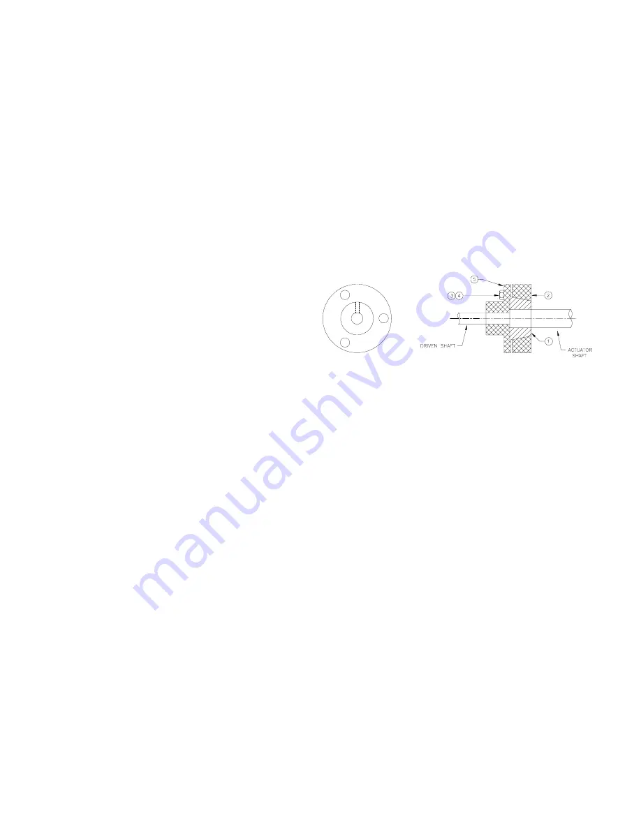
COUPLING (Field Installed)
Jordan Controls has designed a three piece wedge-
lock coupling which can be adjusted to align the
driven device to the actuator output shaft with no
concern as to keyway alignment of the shaft on the
drive device in relation to the spline on the actuator
output shaft.
ADJUSTMENT
1. Slide coupling (5) onto driven shaft.
2. Slide coupling cone (1) and cup (2) onto actuator
shaft.
3. Mount actuator with the two shafts in line and the
shaft ends about inch (3 mm) apart.
4. Turn the shaft of the driven device to the close
position.
5. Run the actuator to the close limit switch.
6. Lock coupling (5) to the driven shaft by pinning or
other suitable method.
7. Slide cone (1) to fit flat in recess of coupling (5).
8. Install three bolts and lockwasher (3) and (4) and
tighten. (20-30 ft. lbs.)
9. Operate the actuator in the open direction and
back to the close direction until the close limit
switch stops the actuator.
10. If the driven shaft does not move to the exact close
position you want, loosen the three bolts and turn
the driven shaft. Tighten the bolts. (20-30 ft. lbs.)
NOTE: Keep the coupling parts clean while
assembling.
See page 21 of this manual for Jordan supplied linkage
components information.
Installation
Summary of Contents for SM-1715
Page 23: ...23...


