


74
P5417009-rev.6
Caution for Insulation Resistance
If the total unit insulation resistance is lower than one megaohm, the compressor insulation
resistance may be lower, due to refrigerant being retained in the compressor. This can occur if the
unit has not been used over prolonged periods of time.
1. Disconnect the cables to the compressor and measure the insulation resistance of the compressor
itself. If the resistance value is over one megaohm, then an insulation failure has occurred in other
electrical parts.
2. If the insulation resistance is less than one megaohm, reconnect the compressor cables from the
inverter PCB. Then, turn on the main power to apply current to the crankcase heater.
After applying current for more than three hours, measure insulation resistance again. (Depending
on the air conditions, length of piping, or refrigerant conditions, it may be necessary to apply the
current for a longer period of time.)
If the GFCI is activated, check the recommended size shown in Table 7.1.
Confirm that field-supplied electrical components (main switch fuse, fuse-free breaker, GFCI breakers, wires,
conduit connectors and wire terminals) have been properly selected according to the electrical data shown in
Table 7.1, and ensure that these components comply with national and local electrical codes.
NOTICE
9.2 Test Run
This test run method is for the wired controller. As for other controllers, refer to Installation and Maintenance
Manual attached to each controller.
(1) Check to ensure that stop valves for high/low pressure gas, low pressure gas and liquid of the outdoor
unit are fully opened.
(In the case of combined outdoor units, check to ensure that all stop valves of the outdoor units are
fully opened.)
(2) Perform the test run of indoor units one by one sequentially, and then check the accordance of the
refrigerant piping system and the electrical wiring system. (If the multiple indoor units are operated
simultaneously, the system accordance cannot be inspected.)
(3) Perform the test run according to the following procedure. Ensure that the unit operates without any
problem.
If two controllers (main and sub) are installed to the system, perform the test run from the main
controller.
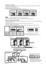
Test Run by Wired Controller
(a) Press and hold “Menu” and “Back/Help” simultaneously for at least 3 seconds. The test run menu
will be displayed.
(b) Select “Test Run” by pressing “
” and press “OK”.
The test run screen will be displayed.
●
The total number of indoor units connected are displayed
on the Liquid Crystal Display (LCD). A twin combination
(one set with two indoor units) is identified as “2 units”,
and a triple combination (of one set with three indoor
units) is identified as “3 units”.
When a “00 unit” is identified, the auto-address function
may be activated. Cancel “Test Run” mode and reset it.
●
If the indicated number is not equal to the actual number of connected indoor units, the auto-
address function is not performed correctly due to incorrect wiring, or electronic noise (EMI).
Turn OFF the power supply, and correct the wiring after checking the following areas: (Do not
repeat turning ON and OFF within 10 seconds.)
* The power supply for the indoor unit is NOT turned ON or there is incorrect wiring.
* A loose connection between indoor units or the wired controller.
* Incorrect Setting of Indoor Unit Address (The indoor unit address is overlapped.)
Test Run Screen
Back
Test Run Setting: 2 units
MODE
:
COOL
SPEED
:
AUTO
ON
Rtrn
Sel.
Adj.


