Y2
Y1
G
RC
C
RH
W1 O/B
Aux D1
D2
RS
Scom
OS
5 pole left top connector
3 pole right top connector
6 pole bottom connector
AUX
D1
D2
Scom
OS
RS
If using the same power source
for the thermostat and heating
loads, install a jumper
across RC and RH.
Remote
Room
Sensor
Remote
Outdoor
Sensor
24 VAC
Thermostat Power
Heat 1
Y2
Y1
G
RC
C
RH
W1
O/B
Separate 24 VAC
Transformer
Y2
Y1
G
RC
C
RH
W1
O/B
R4
To Auxiliary
Heat Circuit
O/B
RC
G
Y1
Y2
Heat Pump Circuit Card
R4-1
R1-1
R2-1
R3-1
VDC Switching Application for Heat Pumps
Aux
Fan
Cool 1
Cool 2
R3
R1
R2
Rev
Valve
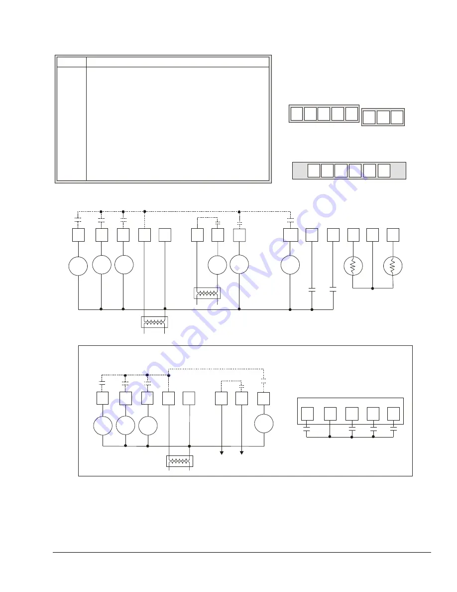
Energizes first stage compressor on a call for heating or cooling
Energizes second stage compressor on a call for heating or cooling
Energizes fan in accordance with the selected fan mode
24 VAC from equipment transformer
24 VAC (common) from equipment transformer
24 VAC for auxiliary heat
Energizes auxiliary heat
Energizes reversing valve (configurable to
energize valve on a call for heat or call for cooling)
Configurable auxiliary output
Configurable digital input
Configurable digital input
Remote room sensor
Sensor common
Outdoor air sensor
Function
Y1
Y2
G
RC
C
RH
W1
O/B
AUX
D1
D2
RS
Scom
OS
Terminal
Note:
Use 24 VAC interface relays
(provided by the user).
T
6
0
0
H
P
P
-2
_
W
ir
in
g
Figure 5: T600HPP-2 Thermostat Wiring Schematic
T600HPP-2 Programmable Thermostat Installation Instructions
3


