


5538117-UIM-B-0319
Johnson Controls Ducted Systems
13
SECTION VI: OPERATION
The following sequences of operation are based on using a single-
stage air conditioning thermostat.
COOLING SEQUENCE OF OPERATION
1.
On a call for cooling, the wall thermostat sends a 24V “Y” signal to
the unit. The unit contactor will close, which energizes the outdoor
fan and the compressor. The 24V signal is also sent to the indoor
blower motor, which will run at the selected cooling speed.
2.
When the demand for cooling has been satisfied, the wall thermo-
stat will remove the 24V “Y” signal from the unit. The contactor will
open and the outdoor fan and the compressor will stop. The indoor
blower has a built-in delay and will continue to run for 60 seconds
after the cooling signal has been removed.
HEATING SEQUENCE OF OPERATION
(for units that have an optional electric heat kit)
1.
On a call for heating, the wall thermostat sends a 24V “W” signal to
the unit. The indoor blower will then start to run at the selected heat-
ing speed. The 24V signal will also go to the sequencer(s) or relays
in the electric heat kit and will turn on the electric heating elements.
2.
When the demand for heating is removed, the wall thermostat will
remove the “W” signal. When the 24V signal is removed from the
electric heat sequencer, the heating elements will turn off. The
indoor blower will continue to run for 60 seconds after the call for
heat is removed.
Electric Heat Limit Switch Operation
6HK three phase heat kits utilize a normally closed low voltage limit
switch, normally closed line voltage limit switch, and a normally closed
fusible link. If the fusible link opens, it must be replaced with the appro-
priate OEM part and the cause must be investigated and corrected.
When the limit switch opens, the heating elements will turn off. The
indoor blower will continue to run. The limit switch will automatically
reset when the temperature has fallen to a normal level, at which time
the heating elements will be turned on again.
* Motor program has 60 second blower off delay on all 5 speed taps.
STARTUP
1.
Check the electrical supply voltage being supplied. Be sure that it is
within the specified range on the unit data plate.
2.
Make sure all electrical connections are tight.
3.
If unit is connected to 208 volt supply power, the control transformer
must be wired accordingly.
4.
Turn unit electrical power on.
5.
Set the room thermostat to COOL mode and lower the desired tem-
perature setting lower than the room temperature to create a call for
cooling.
6.
Measure the total system duct static and set the blower motor cool-
ing speed appropriately per airflow performance tables.
7.
If an optional electric heat kit was installed, make sure the “W”
blower speed is set at or above required speed. See Table 12.
8.
Make sure all units panels are in place and secured, and that an air
filter is installed.
Compressor Rotation
Three-phase, scroll compressors operate in only one direction. If the
scroll is drawing low amperage, has similar suction and discharge pres-
sures, or is producing a high noise level, the scroll is misphased.
If necessary, change the incoming line connection phasing to obtain the
proper rotation.
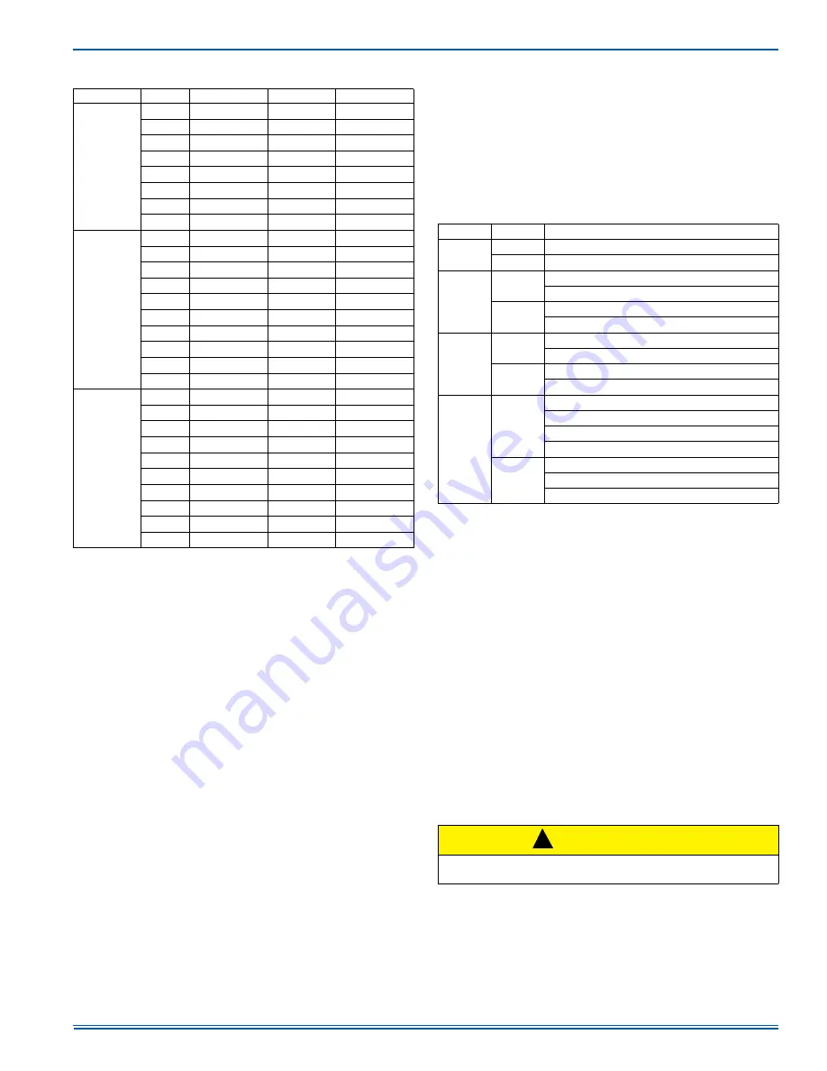
TABLE 14:
Additional Static Resistance
Size (Tons)
CFM
Wet Indoor Coil
Economizer
1
1. The pressure drop through the economizer is greater for 100% outdoor air
than for 100% return air. If the resistance of the return air duct is less than
0.25 IWG, the unit will deliver less CFM during full economizer operation.
Filter pressure drop based on standard filter media tested at velocities not
to exceed 300 ft/min.
Filter/Frame Kit
36 (3.0)
700
0.01
0.00
0.04
800
0.02
0.01
0.06
900
0.03
0.01
0.08
1000
0.04
0.01
0.10
1100
0.05
0.01
0.13
1200
0.06
0.02
0.16
1300
0.07
0.03
0.17
1400
0.08
0.04
0.18
48 (4.0)
1100
0.02
0.02
0.04
1200
0.03
0.02
0.04
1300
0.04
0.02
0.05
1400
0.05
0.03
0.05
1500
0.06
0.04
0.06
1600
0.07
0.04
0.07
1700
0.07
0.04
0.08
1800
0.08
0.04
0.09
1900
0.09
0.05
0.10
2000
0.09
0.05
0.11
60 (5.0)
1100
0.02
0.02
0.04
1200
0.03
0.02
0.04
1300
0.04
0.02
0.05
1400
0.05
0.03
0.05
1500
0.06
0.04
0.06
1600
0.07
0.04
0.07
1700
0.07
0.04
0.08
1800
0.08
0.04
0.09
1900
0.09
0.05
0.10
2000
0.09
0.05
0.11
TABLE 15:
Thermostat Signals
Signal
State
Function
G
ON
Indoor blower instant on
OFF
Indoor blower off after 60-second delay
W
ON
Indoor blower instant on
Electric heat stages on (if so equipped)
OFF
Electric heat stages off (if so equipped)
Indoor blower off after 60-second delay
G & W
ON
Indoor blower instant on in heating speed
Electric heat stages on (if so equipped)
W OFF
Electric heat stages off (if so equipped)
Indoor blower switches to continuous fan speed
G & Y
ON
Outdoor fan on
Indoor blower instant on in cooling speed
Compressor on
System operates in cooling mode
Y OFF
Compressor instant off
Outdoor fan instant off
Indoor blower switches to continuous fan speed
CAUTION
Scroll compressors require proper rotation to operate properly. Fail-
ure to check and correct rotation may result in property damage.
!


