
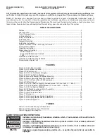


XL EVAPORATIVE COOLING PRODUCTS
INSTALLATION
S140-600 IOM (NOV 07)
Page 9
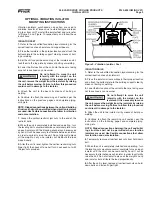
OPTIONAL VIBRATION ISOLATOR
MOUNTING INSTRUCTIONS
Vibration isolators, purchased as an option, are used to
minimize transfer of forces due to vibration/dynamic load-
ing to or from unit. To install the isolator feet and rails, refer
to Figure 9 and Figure 10 respectively and follow these
instructions:
ISOLATOR FEET
1.
Refer to the submitted foundation layout drawing for the
correct location of each isolator and support beams.
2.
Place the isolators in their proper location and attach the
bottom plate to the building support steel by means of bolt-
ing or welding.
3.
Set the unit support beams on top of the isolators and at-
tach them to the top plate by means of bolting or welding.
4.
Lower the fi rst section of the unit onto the beams, taking
care not to overload any one corner.
Do not attempt to move the unit
laterally with the weight on the
isolators. If it is necessary to move
the unit, remove the weight from the isolators by raising
the unit before moving. Failure to follow this procedure
could result in damage to the isolator.
5.
Attach the unit to the beam by means of bolting or
welding.
6.
Continue to attach the remaining unit sections per the
instructions on the previous pages and complete piping,
wiring,etc.
NOTE: Ridged connections between the unit and building
structure shall not be permitted when vibration isolators
are used. Use fl exible connections that allow for vibration
and noise isolation.
7.
Loosen the vertical restraint jam nuts to the end of the
restraint bolts.
8.
When the unit is completely installed and operating, turn
the leveling bolts counterclockwise several complete turns
on each isolator until the blocking channel can be removed
by hand. It will be necessary to alternate between isolators
in order to uniformly raise the unit. Do not attempt to place
all the weight on any one isolator, but distribute the load
proportionally.
9.
After the unit is level, tighten the vertical restraining nuts
fi nger tight, then back off one half turn. Lock each nut with
the jam nuts provided.
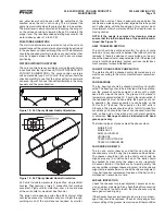
Figure 9 - Vibration Isolator Feet
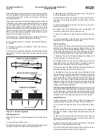
ISOLATOR RAILS
1.
Refer to the submitted foundation layout drawing for the
correct location of each isolator rail.
2.
Place the isolator rail assemblies in their proper location
and attach the bottom plate to the building support steel by
means of bolting or welding.
3.
Lower the fi rst section of the unit onto the rails, taking care
not to overload any one corner.
Do not attempt to move the unit
laterally with the weight on the
isolators. If it is necessary to move
the unit, remove the weight from the isolators by raising
the unit before moving. Failure to follow this procedure
could result in damage to the isolator.
4.
Attach the unit to the isolator rail by means of bolting or
welding.
5.
Continue to attach the remaining unit sections per the
instructions on the following pages and complete piping,
wiring, etc.
NOTE: Ridged connections between the unit and build-
ing structure shall not be permitted when vibration
isolators are used. Use fl exible connections that allow
for vibration and noise isolation.
6.
Temporarily remove all vertical locknuts from hold-down
bolt.
7.
When the unit is completely installed and operating, turn
the leveling nuts clockwise several complete turns on each
isolator until the shim can be removed by hand. It will be
necessary to alternate on each isolator in order to uniformly
raise the unit. Do not attempt to place all the weight on any
one isolator, but distribute the load proportionally.
8.
After the unit is level, replace all vertical locknuts on hold-
down bolts and fasten fi nger tight.


