


XL EVAPORATIVE COOLING PRODUCTS
INSTALLATION
S140-600 IOM (NOV 07)
Page 8
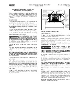
The second step of the installation is to mount the coil sec-
tion as follows:
1.
Some units are shipped with the fan guards in the pan
section for shipping purposes. In these cases, remove fan
guards from pan section and install on the front of the unit
before joining fan and coil sections.
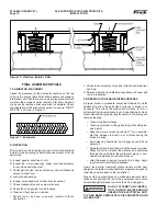
2.
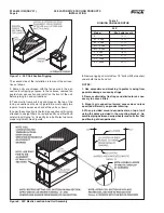
Take mastic from parts box and place on the top of the
fan & pan section as shown in Figure 8. Be sure to apply two
layers of mastic across each end of the unit as shown.
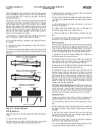
3
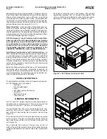
. Lower the coil section to the fan & pan section with rigging
attached to all eight lifters. For extended lifts, use lifters and
safety slings (Figure 7c). Use drift pins in bolt holes to ensure
proper alignment. See Figure 8.
NOTES:
1. Use spreaders and blocking to protect casing from
possible damage caused by slings.
2. Remove eliminator tie straps and eliminators as nec-
essary to access lifters.
3. Mount coil connection toward access door unless
specifi ed differently on product drawing.
4. When provided, mount desuperheater on top of unit
using the holes provided in the mounting bracket. As-
semble piping between desuperheater and coil after fi nal
positioning of desuperheater.
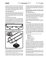
Figure 7c - XLP Coil Section Rigging
XLP
Model
Min. Cable Length
S
14
ft
M - 2 Fan
13 ft
M - 3 Fan
17 ft
ML - 2 Fan
15 ft
ML - 3 Fan
20 ft
L - 2 Fan
16 ft
L - 3 Fan
21 ft
XL - 2 Fan
17 ft
XL - 3 Fan
22 ft
Table 3
RIGGING CABLE LENGTHS
Figure 8 - XLP Mastic Location And Unit Assembly
4.
Remove rigging and install four 1/2" bolts with fl at washers
under both the bolt and nut.


