


XL EVAPORATIVE COOLING PRODUCTS
OPERATION
S140-600 IOM (NOV 07)
Page 11
OPERATION
Frick
®
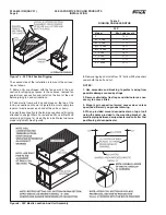
Evaporative Condensers remove heat from the fl uid
circulating in the coil by recirculating water over the outside of
the coil and blowing air up through the wetted coil. The water
that is recirculated over the outside of the coil is stored in the
pan section at the bottom of the unit, and is pumped over the
coil through spray nozzles by the spray pump mounted on the
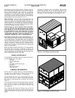
end of the unit. The fans are located on the side of the XLC
Centrifugal Fan Units in the dry entering air stream and are
driven by a motor that is mounted on top of the fan section.
The fans on the XLP Vane Axial Fan Units are located above
the pan in the pan/fan section in the dry entering air stream
and are driven by motors that are located below the fans.
The coolers are designed to provide maximum capacity when
both the spray system and the fans are running, and only
partial capacity when either the spray system or the fans are
running alone. A practical method of capacity control is to
cycle the fan and spray pump motors with a thermostat or
pressure switch that senses the fl uid leaving the unit. Care
must be taken, however, to cycle the fans off fi rst, then the
spray pump. This enables the solids left behind to be washed
into the pan, by the spray water, where they can be bled off
to the drain.
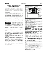
When provided, capacity control dampers are mounted
in the discharge throat of the fans on the XLC units or on
the air discharge of the XLP units for closer control of fl uid
temperature or pressure. These dampers are controlled
by a modulating damper actuator and a remote bulb-type
temperature or pressure controller. The sensing bulb of the
controller should be installed in the fl uid piping leaving the
unit, and the controller should be wired to the damper actua-
tor as shown on the appropriate wiring diagram. The damper
actuator contains an end switch that should be used to turn
off the fan motor when the dampers are fully closed.
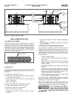
Units provided with positive closure discharge dampers are
designed to reduce heat loss from the unit when it is not in
operation by eliminating the chimney effect. The dampers are
operated by an “On-Off” damper actuator, and are positioned
closed when the spray pump motor is off, and open when
the spray pump motor is on. The actuator should be wired
as shown on the appropriate wiring diagram.
COLD WEATHER OPERATION
Frick
®
Evaporative Condensers are suitable for most cold
weather applications when supplied with proper capacity
control and freeze protection.
A common application for Vane Axial units is to cycle the
operating fans to achieve capacity control. Typically, the fans
are cycled off as capacity drops and fi nally, the pump is shut
off. In cold weather operation, Frick
®
recommends that the
pump should be the fi rst item shut off to achieve capacity
control. By running the unit dry in cold applications, the unit’s
drive is protected from ice formation. Ice forms when the spray
water causes moist air to migrate out of idle fans where it
condenses and freezes on cold metal surfaces.
As long as the Evaporative Condensers are in operation
with a load, with capacity control dampers, the recirculating
pan water will not freeze. However, the pan water must be
protected when Evaporative Condensers are under a “no
load” condition with fans and spray pumps off. An indoor
remote sump and pump is the best means of avoiding pan
water freezing in an idle Evaporative Condenser. With this
remote sump system, the pan water is always drained to
the indoor remote sump whenever the recirculating water
pump is stopped.
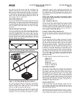
Because of the Evaporative Condenser location or space
limitations, a remote sump installation may be impractical.
In such cases, supplementary heat must be supplied to the
pan water. The Evaporative Condenser will then need to be
furnished with an electric pan heater. This heater will provide
suffi cient heat to keep the spray water in the pan from freez-
ing when the unit is not running. The heater is controlled by
a thermostat that senses the pan water temperature, and is
factory set at 42°F. The heater is protected by a low water
cutout switch that prevents the heater from operating if the
pan water level is below the heater element. In addition to pro-
tecting the pan water, all exposed water piping, including the
pump suction line, pump, pump discharge piping (up to the
overfl ow connection), and the make-up water lines, should be
traced with electrical heat tape and insulated. Some Evapo-
rative Condenser installations will permit all spray water to
be drained from the pan during cold weather operation. This
permits dry operation of the Evaporative Cooler or Condenser
when the load and ambient temperatures are low.
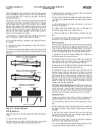
Units that require year-round operation in a freezing climate
should be equipped with an electric pan water level control
package. This package ensures a constant water level with-
out adjustment and also maintains very close control of the
pan water level. The system consists of a weather-protected
electric fl oat switch with stilling chamber mounted on the pan
section and a weather-protected solenoid valve mounted on
the water makeup connection. When this system is used, it
replaces the standard mechanical water makeup valve.


