


XL EVAPORATIVE COOLING PRODUCTS
INSTALLATION
S140-600 IOM (NOV 07)
Page 10
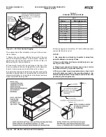
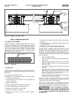
Figure 10 - Vibration Isolator Rails
FINAL ASSEMBLY DETAILS
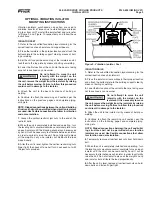
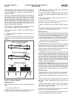
1. ELIMINATOR PLACEMENT
Check the placement of the eliminator sections on the top
of the unit to ensure that all eliminator sections are properly
interlocked and that there are no openings present which
will allow the escape of water droplets. Eliminator tie-down
straps can be removed after assembly is complete. Check
the orientation of the eliminator sections to ensure "RIGHT
SIDE UP" as shown in Figure 11.
2. INSPECTION
Prior to start-up, the following services, which are described
in detail in the operating and maintenance manual, must be
performed:
A. Inspect general condition of unit.
B. Inspect fan, motors, bearings, drives, and locking collars
for condition and alignment.
C. Check belt tension and condition per the maintenance
manual instructions.
D. Lubricate all bearings.
E. Inspect spray headers and heat transfer section.
F. Check makeup valve and sump water level.
G. Check fans and guards for obstructions.
H. Clean and fl ush pan and strainer.
I. Rotate fan(s) by hand to ensure rotation without
obstruction.
J. Check fans and pumps for correct rotation and electrical
hook-up.
K. See the Operation and Maintenance Manual for new belt
run-in procedures.
3. BREAKING IN THE GALVANIZED SURFACES
A proper break-in procedure should be followed for water
treatment to allow the galvanized surfaces to break in or
passivate. This allows the galvanized surfaces to form a
self-protecting zinc carbonate layer. A qualifi ed water treat-
ment specialist can provide specifi c details, but following are
some guidelines.
• Clean all wetted surfaces.
• Touch up scratches in the galvanizing with cold galva-
nized paint.
• Keep the water as close neutral (pH 7.0) as possible.
Must be between 6.5 and 7.5 at all times during the
break-in period.
• Avoid cleaning chemicals in pH ranges above 8.0 and
below 6.0.
• Operate under minimal load during the break-in period.
When the unit is installed, the water can be circulated
through the unit before the refrigerant piping is con-
nected to begin the passivation process.
• After the break-in period, typically 30-45 days, begin
regular water treatment procedures.
Again, local water treatment professionals will be best
equipped to create a water treatment program designed to
meet the specifi c needs of the installation.
Proper start-up procedures and scheduled periodic main-
tenance will prolong the life of the equipment and ensure
trouble-free performance for which the unit is designed.
DO NOT ATTEMPT ANY INSPEC-
TION AND/OR MAINTENANCE
UNLESS THE ELECTRICAL SUP-
PLY HAS BEEN COMPLETELY DISCONNECTED AND
LOCKED OUT.
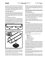
Figure 11 - Eliminator


