


XL EVAPORATIVE COOLING PRODUCTS
TABLE OF CONTENTS
S140-600 IOM (NOV 07)
Page 2
TABLE OF CONTENTS
Preface ................................................................................................................................ 3
Job Inspection ...................................................................................................................... 3
Transit Damage Claims ........................................................................................................ 3
Unit Identifi cation ................................................................................................................. 3
Safety Requirements ........................................................................................................... 3
Installation Tools .................................................................................................................. 4
General Information ............................................................................................................. 4
Installation Instructions ........................................................................................................ 5
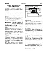
Optional Vibration Isolator - Mounting Instructions .............................................................. 9
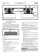
Final Assembly Details ...................................................................................................... 10
Operating Instructions ........................................................................................................ 11
Maintenance Instructions ................................................................................................... 12
Water
Treatment............................................................................................................. 12
Suggested Maintenance Intervals ................................................................................. 12
Fans
............................................................................................................................... 15
Operation and Maintenance .............................................................................................. 15
Operation and Maintenance Schedule .............................................................................. 16
Recommended Spare Parts .............................................................................................. 17
FIGURES
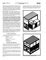
Figure 1a. XLC I-Beam Location .......................................................................................... 4
Figure 1b. XLP I-Beam Location .......................................................................................... 4
Figure 2. Platform Layout ..................................................................................................... 5
Figure 3a. XLC Pan Coil Section Rigging ............................................................................ 5
Figure 3b. XLC Fan Section Rigging .................................................................................... 5
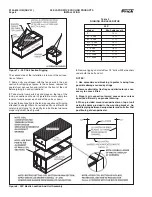
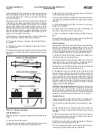
Figure 4a. Mastic Placement For Blower Mounting ............................................................. 6
Figure 4b. Blower Assembly Mounting Instructions ............................................................. 6
Figure 5. XLC Unit Assembly with Desuperheater ............................................................... 6
Figure 6. Platform Layout ..................................................................................................... 7
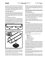
Figure 7a. XLP Fan Section Rigging
(All models except 1570-2 and 1660-2 — 1880-2)
............. 7
Figure 7b. XLP Fan Section Rigging
(Models 1570-2 and 1660-2 — 1880-2)
............................ 7
Figure 7c. XLP Coil Section Rigging .................................................................................... 8
Figure 8. XLP Mastic Location and Unit Assembly .............................................................. 8
Figure 9. Vibration Isolator Feet ........................................................................................... 9
Figure 10. Vibration Isolator Rails ...................................................................................... 10
Figure 11. Eliminator .......................................................................................................... 10
Figure 12. XLC Spray Header Nozzle Orientation ............................................................. 13
Figure 13. XLP Spray Header Nozzle Orientation ............................................................. 13
Figure 14. Sheave Alignment ............................................................................................. 14
TABLES
Table 1. XLC Foundation Layout Dimensions ...................................................................... 5
Table 2. XLP Foundation Layout Dimensions ...................................................................... 7
Table 3. Rigging Cable Lengths ........................................................................................... 8
NOTE: Installation, operation, maintenance, and repair of this equipment should only be accomplished by qualifi ed person-
nel. Failure to follow this note may result in improper installation and operation of the equipment and personal injury.
Frick's
XL Condensers are designed to ensure energy effi cient operation and years of dependable, trouble-free service. To
maximize service life, it is important to follow the recommended installation, operation, and maintenance procedures outlined in
this manual. Be sure to follow the Recommended Maintenance Table and read the detailed instructions of each procedure. Care
taken to follow these instructions will directly affect the satisfactory operation and reliability of the system.
Indicates an imminently hazardous situation which, if not avoided, will result in death
or serious injury.
Indicates a potentially hazardous situation or practice which, if not avoided, will result
in death or serious injury.
SAFETY PRECAUTION DEFINITIONS
Indicates a potentially hazardous situation or practice which, if not avoided, will result
in damage to equipment and/or minor injury.
NOTE:
Indicates an operating procedure, practice, etc., or portion thereof which is essential to
highlight.


