


Network Room Module Technical Bulletin
6
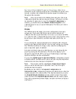
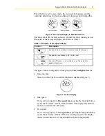
Figure 3 shows the layout and symbols of the LCD, and Table 2 describes
the symbols.
Figure 3: LCD Symbol Options
Table 2: Symbols on the LCD
Control Description
Temperature display digits
Fan speed status bars – low, medium, and high speed (high
speed shown)
°
C
Celsius temperature unit
°
F
Fahrenheit temperature unit
AUTO
The Auto icon indicates that the fan is in auto mode.
OFF
The Off icon indicates that the fan has been manually set to Off
(not running).
The Maintenance icon indicates an off-normal condition that
requires attention.
The Occupancy Mode icon indicates the occupied/unoccupied
mode of the controller (LP-NRM5xx-000C and LP-NRM6xx-
000C Series only).
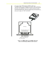
Functions and Setup of the Network Room Module
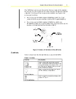
The NRM is a network device with no hardware inputs or outputs and
connects to the Facility Explorer controller via the display (or local link)
bus. All the communication access and setup of the NRM is done through
the controller where the NRM is connected. The configuration properties
of the NRM are set in the Room Sensor object in the controller when the
control application for the controller is generated in the FX Builder tool.
When the application is downloaded to the controller, you use the
FX CommPro N2, LON, or BACnet commissioning tool to monitor the
network variables of the NRM in the Room Sensor object through the
network profile of the controller.
This section describes the various functions and display features of the
NRM, the network variables used by each function, and the configuration
properties used to set up each function.