


Network Room Module Technical Bulletin
19
Note:
The device does not require a ground/earth connection.
I
MPORTANT
: Cables and wiring at Safety Extra Low Voltage (SELV) and Class
2 wiring (North America) must be separated from power line voltage wiring. A
minimum separation distance of 30 cm (12 in.) is recommended. Do not run extra
low voltage cables parallel to power line voltage cables for long distances greater
than 3 m (10 ft). Do not run extra low voltage wiring close to transformers or high
frequency generating equipment.
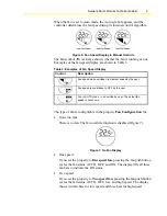
Addressing
Non-addressable NRM models have a fixed physical address of 191. For
those models which are addressable, the NRM’s address must be set using
its dual-switch DIP switch block, located on the printed wiring board. See
Figure 12 and Table 8 for details on addressing the NRM.
Note:
You must cycle power to the NRM (disconnect/reconnect the
NRM or cycle power to the field controller) for the address change to take
effect.
Figure 12: Dual-Switch DIP Switch Block
Table 8: NRM Addressing
DIP Switch Address
Switch 2
Switch 1
191
OFF OFF
192
OFF ON
193
ON OFF
194
ON ON