


Network Room Module Technical Bulletin
18
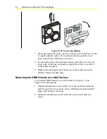
Wiring
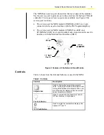
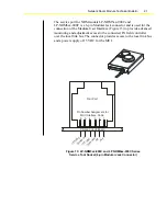
Terminations are made on the terminal block in the base of the module,
which is accessible after removing the cover from the base. The screw
terminals accept up to 1.5 mm
2
(16 AWG) wires, and Figure 11 shows the
terminal block connections. Complete and verify all wiring connections
before you apply power to the module.
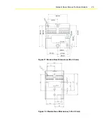
12 13 14 11
POWER
SUPPLY
INPUT
N2 RT+
COM
N2 RT-
Figure 11: Wiring to the NRM
Follow this information when you wire an FX controller to an NRM:
!
CAUTION:
Risk of Electric Shock.
Disconnect power supply
before making electrical connections to avoid electric shock.
I
MPORTANT
: The LP-NRM0xx-000C Series NRM accepts
VAC
or
VDC
power.
The LP-NRM5xx-000C and LP-NRM6xx-000C Series accept
VDC
power only.
•
Connect power to terminals 11 (+ VDC or VAC) and 14 (- VDC or
VAC). You may take power from the FX controller (15 VDC).
Note:
The COM terminal of the NRM is connected to the common
potential of the FX controller. If an independent power supply is used
for the NRM, ensure the proper connection of the multiple power
supplies to avoid a short circuit through the NRM module or FX
controller.
•
Use screw terminals 12 (N2 RT+), 13 (N2 RT-) and 14 (COM) to
connect to the FX controller display (local ink) bus terminals (LL+,
LL-, and COM, respectively). This is an RS-485 bus where the wires
are polarity sensitive. A common or reference wire is required and the
N2 Open protocol is used. All the installation rules for the N2 bus
apply to this connection.
•
If shielded cable is used for the network wiring, connect the shields
together and insulate with tape. Do not use the COM terminal for cable
shields.