8
ZZ1027/3
13
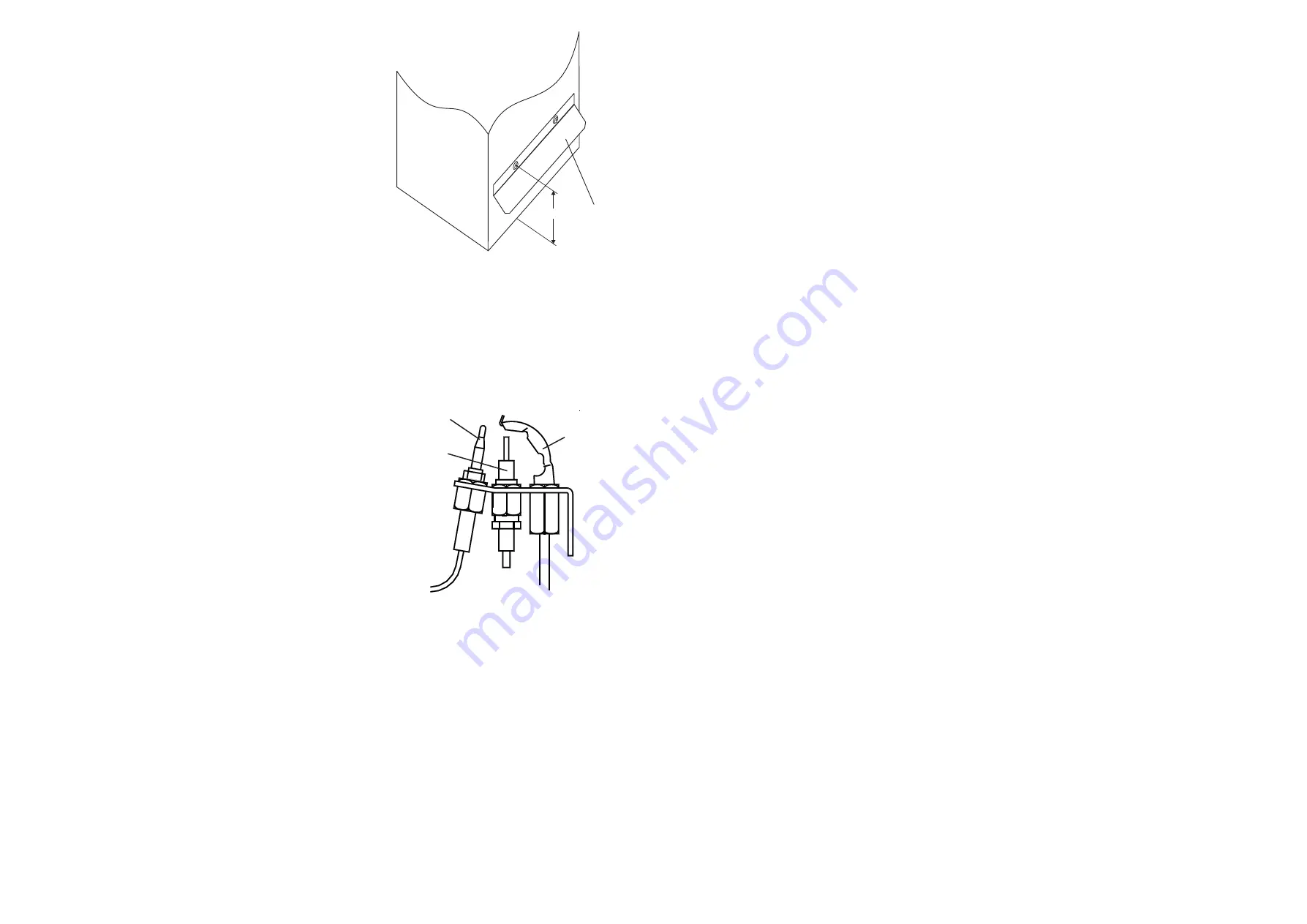
130mm
Heater
Deflector
Plate
Fig. 3
Deflector Plate
Thermocouple
Pilot Burner
Electrode
Fig. 4
Pilot Burner Assembly
6.3
IGNITION OF PILOT AND MAIN BURNERS:
WARNING:
If the Pilot Burner is extinguished either intentionally or
unintentionally, no attempt should be made to relight the gas for a minimum of 3
minutes. Ensure that the Electrical supply, time control and Selector switches
are set to ‘
OFF
’
.
6.3.1
Set the room thermostat to its lowest or
OFF
setting.
6.3.2
On the Multifunctional Control, remove the Outlet Pressure test
point cover, and a fit pressure test gauge (refer Fig. 5)..
6.3.3
Turn the heater Gas supply
ON
, test for gas soundness and
purge the whole gas pipe as described in BS 6891.
6.3.4
Referring to Fig .5, press and hold the OPERATING CONTROL,
and whilst observing the Pilot Burner, repeatedly press the Piezo
igniter button until the Pilot Burner ignites.
6.3.5
After 20 seconds release the OPERATING CONTROL and let it
spring out; ensure that the Pilot Burner remains alight. If the Pilot
Burner extinguishes, rotate the OPERATING CONTROL clockwise
to the ‘l’ position and ensure that the OPERATING CONTROL is
fully reset. Wait three minutes and repeat steps 6.3.4 and 6.3.5
until the Pilot Burner remains alight.
6.3.6
Ensure that the pilot flame envelops the thermocouple tip, adjusting the Pilot Adjuster as required (Refer Figs. 4 and
5).
6.3.7
Set the Heater Electricity supply ON.
6.3.8
Set the Time Control to the required Heating On periods.
6.3.9
Set the Selector switch to ‘TIMED’.
6.3.10 Set the room thermostat to MAXIMUM.
6.3.11 Ensure that the Main Burner has now ignited.
6.3.12 Test for gas leakage at the supply, Multifunctional Control, and
Pilot and Main Burners using a proprietary detection fluid, sealing
any leaks found.
6.3.13 Allow the heater to operate for a minimum of 15 minutes to ensure
stability.
6.4
MAIN BURNER PRESSURE TEST:
IMPORTANT: AIR HEATER BURNERS ARE FACTORY SET TO PROVIDE A
NOMINAL RATE OUTPUT AS DETAILED IN SUB PARA 1.2
6.4.1
Referring to Table 4 and Fig. 4 below, ensure that the pressure test
gauge indicates the correct burner pressure.
6.5
EXTINGUISHING OF PILOT AND MAIN BURNERS:
6.5.1
On the Multifunctional Control, rotate the OPERATING CONTROL
clockwise to the ‘l’ position and ensure that the OPERATING CONTROL fully resets, and both Pilot and Main
Burners are extinguished.
6.5.2
On the Multifunctional Control, remove the pressure test gauge and refit the Outlet Pressure test point cover, and
test for gas soundness.
6.6
TEMPERATURE RISE CHECK:
6.6.1
Ignite the Pilot and Main Burners and allow to operate for 15 minutes to ensure stability.
6.6.2
With the Main Burner operating continually, check that the temperature rise across the heater is between 45
O
C -55
O
C,
setting the fan speed accordingly, (decrease the fan speed to increase the temperature rise). The fan speed is
adjusted by selecting the fan speed at the electrical control panel (decrease voltage selection to decrease fan speed).
Note: TAPPING 1 = 150V, TAPPING 2 = 170V,
TAPPING 3 = 190V,
TAPPING 4 = 210V,
TAPPING 5 = 230V.
8.9.6
Disconnect 2 x TTB connections.
8.9.7
Disconnect the Multifunctional Control connections.
8.9.8
Release 4 x 4mm screws securing the Electrical Assembly to the heater cabinet and remove the Electrical Assembly,
releasing wiring from cable clamps and grommets as required..
8.9.9
Refitting or replacement is in reverse order.
8.10
TIME CONTROL REMOVAL:
8.10.1 Ensure that the electrical supply is isolated.
8.10.2 Release the securing screw situated on the lower face of the Time Control and remove it by partially withdrawing
bottom of the Time Control and then lifting upwards.
8.10.3 Disconnect the Time Control electrical connections from its integral terminal strip.
8.10.4 Refitting or replacement is in reverse order.
8.10.5 Set the Time Control to the required ON and OFF times.
8.10.6 Set the Time Control to the correct time.
8.11
FAN DELAY CONTROL AND LIMIT SWITCH REMOVAL:
8.11.1 Ensure that the electrical supply is isolated.
8.11.2 Remove the appliance lower and upper doors.
8.11.3 Release 2 x 4mm screws securing the Limit Switch cover and withdraw the cover.
8.11.4 Disconnect the required control/switch.
8.11.5 Release 2 x securing screws and remove the required control/switch.
8.11.6 Refitting or replacement is in reverse order.
8.12
SPILLAGE MONITOR DEVICE (TTB) REMOVAL:
8.12.1 Ensure that the electrical supply is isolated.
8.12.2 Remove the appliance lower and upper doors.
8.12.3 Remove the Air Circulation fan as detailed in para 8.8.
8.12.4 Cover the aperture to the heat exchanger in the top shelf to prevent objects falling into the heat exchanger.
8.12.5 Release and remove 6 x screws securing the fan compartment rear access panel, and withdraw the panel.
8.12.6 Disconnect the TTB terminal block plug from the terminal block socket, situated on the compartment rear bulkhead,
remove the grommet rearwards and pass the terminal block through the aperture in the rear bulkhead.
8.12.7 Release and remove the 5mm nut and lock washer securing the TTB Assembly to the Draught Diverter, and withdraw
the TTB Assembly.
8.12.8 Refitting or replacement is in reverse order.
8.13
HEAT EXCHANGER ACCESS:
8.13.1 Release 2 x securing screws and remove heat exchanger access caps and gaskets.
8.13.2 Remove the heat exchanger baffles.
8.13.3 Reassembly is in reverse order.
NOTE: When reassembling, ensure that the baffles are pushed fully home and that the access caps are fully sealed. In the event of
heat exchanger replacement being necessary, contact Johnson and Starley Service Department.
9.
DEFECT DIAGNOSIS
9.1
IMPORTANT: If an electrical defect occurs after installation of the appliance; preliminary earth continuity, polarity, and
resistance to earth checks should be carried out with a multimeter. On completion of anymaintenance/fault-finding task
that has required the breaking and remaking of electrical connections, then checks of continuity, polarity, and resistance to
earth must be repeated.
9.2
WARNINGS:
9.2.1
When purging or checking gas supplies, ensure that the ventilation to the room or cupboard is adequate, and that all
naked lights are extinguished.


