background image

22

4.

 DUCT SYSTEM

All ductwork 

MUST

 be mechanically secured and sealed with good quality ducting tape.

4.1

RETURN AIR

4.1.1

Room-sealed appliances may be installed without return air ducting provided that the path between the return air
grille and the appliance return air inlet is protected in such a manner that the required airflow will be maintained at
all times. The return air grille should have a free area of not less than 0.06m

2

 (93 in

2

).

4.1.2

An adequate and unobstructed return air path is essential from areas served by a directly ducted return and to
which warm air is delivered. All such rooms should be fitted with relief grilles which have a free area of
0.0088m

2

/kW (1 in

2

/250Btu/h) of heat supplied to the room. The only exceptions are kitchens, bathrooms and

w.c’s.

4.2

WARM DELIVERED AIR

4.2.1

All ductwork, including riser ducts, should be fully insulated with 50m (2 in.) of fibreglass or similar. If short
extended duct runs are taken below floor level, these should be similarly insulated and in addition, wrapped with a
sound vapour proof barrier and protected from crushing.

4.2.2

The duct system should be carefully designed to suit the needs of its specific heating requirements and building
layout. The type of duct system, i.e., radial/extended plenum/stepped, should be installed using the least number of
fittings to minimise the resistance to air flow.

4.2.3

The base duct, which equalises the air pressure to supply ducts, shall be constructed to support the weight of the
heater, which shall be secured to the plenum with screws on at least two sides, and sealed using self-adhesive
foam strip, ducting tape or sealing compound. All ducting and blanking plates shall be mechanically secured and
sealed.

5.

INSTALLATION

5.1

SIDE RETURN AIR

If return air is to be introduced via the side of the appliance, it will be necessary to prepare it prior to installation. Return
air ducting may be connected to either side of the heater as follows:

5.1.1

Remove the air filter, front cover and the air circulation fan.

5.1.2

Cut a hole in the chosen side of the fan compartment. The knock outs will determine the size and position.

5.1.3

Remove and the filter frame retaining screws and remove the filter frame.

5.1.4

Position the filter frame centrally over the prepared hole so that the front of the frame is flush with the front of
the heater.

5.1.5

Using the frame as a template, mark and drill the 6 x 3.2mm dia. frame fixing holes.

5.1.6

Secure the filter frame to the side of the heater using the screws previously removed.

5.1.7

Refit the air circulation fan, front cover and air filter.

5.1.8

Using suitable material, manufacture a plate to cover the original return air opening in the top of the air heater, and
secure with self tapping screws (not provided).

5.2

SE-DUCT PREPARATION

5.2.1

Ensure that the existing air heater has first been removed.

IMPORTANT:   Many SE-ducts are constructed from asbestos-based materials, and due to dimensional
variations between Johnson & Starley and other manufacturers appliances, a certain amount of rework
will be required on the SE-duct by REGISTERED CONTRACTORS.

5.2.2

In some circumstances, the SE-duct may be completely exposed and special components needed to complete the
installation. Consult Johnson & Starley Service Department if this situation is encountered.

5.2.3

Referring to Fig. 2, NOTE THE DATUM POINTS INDICATED before proceeding. 

 A Sealing

Template Kit (ST25) is available for cutting the holes in the SE-duct.

5.2.4

Thoroughly clean and replace the sealing material from the top of the existing base duct.

5.2.5

The holes in the SE-duct 

MUST

 correspond with the positions ‘

A

’ and ‘

B

’ as shown in Fig. 2, 138mm (5.5 in.)

minimum diameter, 152mm (6.0in.) maximum diameter, and clear the duct of all resulting debris. Should the
original heater be a SUGG Type 22/WH ‘Halcyon’, the existing bottom hole is suitable for use.

5.2.6

Seal the redundant hole/s in the SE-duct using a suitable cement or blanking material, to ensure a good flat surface
on both the inner and outer faces of the duct wall.

IMPORTANT:

Any debris which falls into the SE-duct MUST BE REMOVED.

3

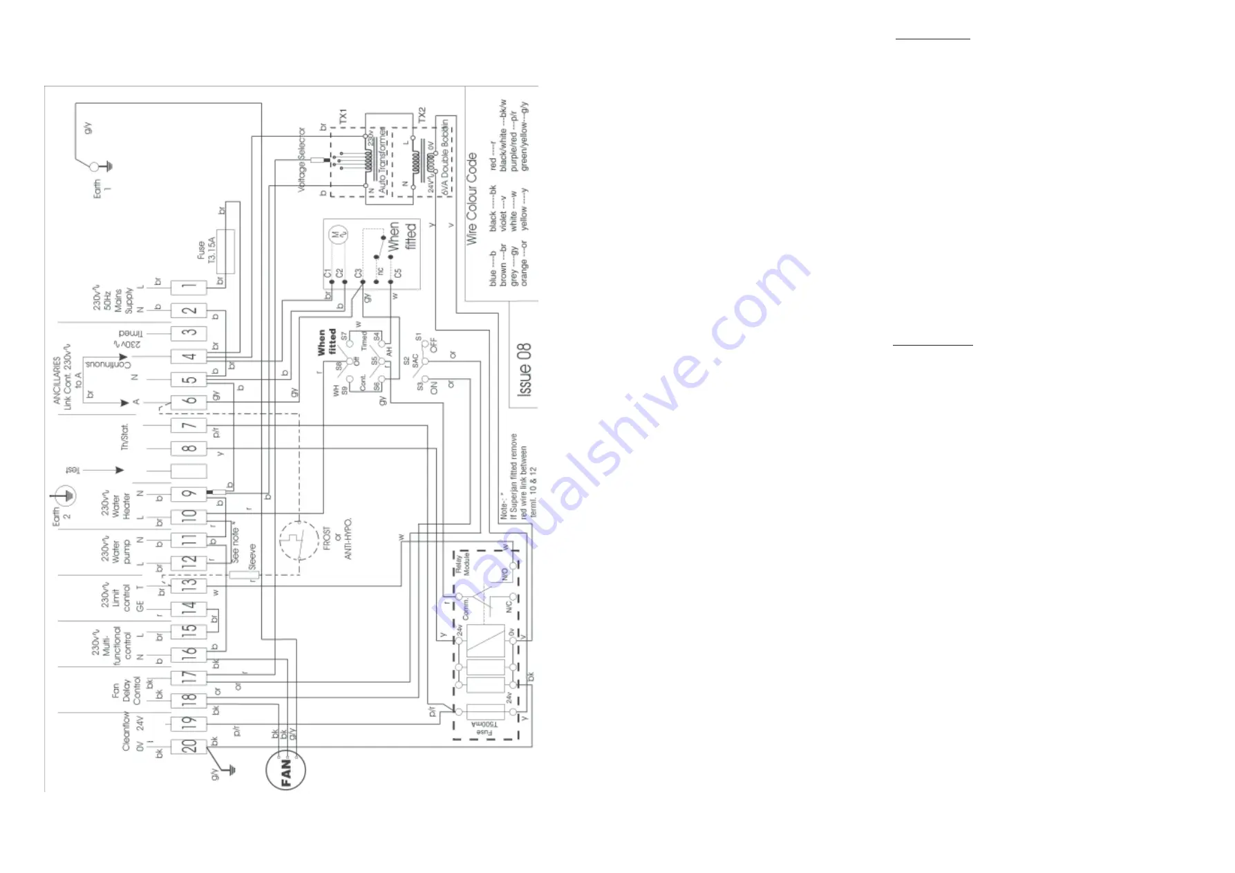
Fig. 7b, BASIC CONTROL CIRCUIT DIAGRAM

r

Summary of Contents for HI-SPEC J25SC Series

Page 1: ...PARES HI SPECJ25SC KEY G CNo MFR SNo DESCRIPTION QTY 1 BOS02064SP Fan Assembly 1 2 T193 0145000 FilterAssembly 1 3 378466 BOS02031 Time Control 1 4 381627 1000 0701140 Multifunctional Control 1 5 2329...

Page 2: ...ent must be not less than 75mm 3 in However if clearances are less than 75mm the internal surface of the compartment must be lined with non combustible material The compartment must be of a fixed rigi...

Page 3: ...he air filter front cover and the air circulation fan 5 1 2 Cut a hole in the chosen side of the fan compartment The knock outs will determine the size and position 5 1 3 Remove and the filter frame r...

Page 4: ...5 4 4 Apply a suitable mastic not provided to the spigot flanges and insert them into their respective apertures and seal them to the face of the SE duct wall 5 4 5 Position the larger rope ring seal...

Page 5: ...door or windows or on an outside wall iii Where affected by warm air ducts diffusers waste pipes or the heater itself iv Where subject to vibration c Connect Thermista stat Room thermostat wires to c...

Page 6: ...MAXIMUM 6 3 11 Ensure that the main burner has now ignited 6 3 12 Test for gas leakage at the supply Multifunctional control Pilot and Main burners using proprietary detection fluid and sealing any le...

Page 7: ...ch OFF the electrical supply to the air heater 6 8 3 Release the securing screw and hinge down the fan chamber door 6 8 4 Disconnect the air circulation fan as follows a System E T models disconnect t...

Page 8: ...s etc Outlet faces may require partial blanking in order to achieve this 6 9 3 Set the SUMMERAIRFLOW switch to O 6 9 4 Ignite the Pilot and Main burners as detailed in sub paras 6 3 4 to 6 3 7 6 9 5 S...

Page 9: ...arry out a complete functional test of the appliance in accordance with Commissioning Instructions at Sect 6 1 to 6 8 inclusive Replace any sealing gasket or insulation that is damaged before re commi...

Page 10: ...Thermocouple lock nut from the Pilot Burner Assembly and Multifunctional Control and withdraw the Thermocouple taking care to avoid damage to the capillary 8 5 3 Release the Igniter electrode lock nut...

Page 11: ...0 3 Disconnect terminals 21 to 33 from the Electronic module 8 10 4 Release the 2 x screws and nuts securing Electronic module to Electrical assembly and remove module 8 10 5 Refitting or replacement...

Page 12: ...YSTEM E T models a When carrying out any electrical testing a test meter MUST be used since low resistance test devices can cause damage to the Electronics module b Before commencing defect diagnosis...

Page 13: ...YSTEM E T models a When carrying out any electrical testing a test meter MUST be used since low resistance test devices can cause damage to the Electronics module b Before commencing defect diagnosis...

Page 14: ...0 3 Disconnect terminals 21 to 33 from the Electronic module 8 10 4 Release the 2 x screws and nuts securing Electronic module to Electrical assembly and remove module 8 10 5 Refitting or replacement...

Page 15: ...Thermocouple lock nut from the Pilot Burner Assembly and Multifunctional Control and withdraw the Thermocouple taking care to avoid damage to the capillary 8 5 3 Release the Igniter electrode lock nut...

Page 16: ...arry out a complete functional test of the appliance in accordance with Commissioning Instructions at Sect 6 1 to 6 8 inclusive Replace any sealing gasket or insulation that is damaged before re commi...

Page 17: ...s etc Outlet faces may require partial blanking in order to achieve this 6 9 3 Set the SUMMERAIRFLOW switch to O 6 9 4 Ignite the Pilot and Main burners as detailed in sub paras 6 3 4 to 6 3 7 6 9 5 S...

Page 18: ...ch OFF the electrical supply to the air heater 6 8 3 Release the securing screw and hinge down the fan chamber door 6 8 4 Disconnect the air circulation fan as follows a System E T models disconnect t...

Page 19: ...MAXIMUM 6 3 11 Ensure that the main burner has now ignited 6 3 12 Test for gas leakage at the supply Multifunctional control Pilot and Main burners using proprietary detection fluid and sealing any le...

Page 20: ...door or windows or on an outside wall iii Where affected by warm air ducts diffusers waste pipes or the heater itself iv Where subject to vibration c Connect Thermista stat Room thermostat wires to c...

Page 21: ...5 4 4 Apply a suitable mastic not provided to the spigot flanges and insert them into their respective apertures and seal them to the face of the SE duct wall 5 4 5 Position the larger rope ring seal...

Page 22: ...he air filter front cover and the air circulation fan 5 1 2 Cut a hole in the chosen side of the fan compartment The knock outs will determine the size and position 5 1 3 Remove and the filter frame r...

Page 23: ...ent must be not less than 75mm 3 in However if clearances are less than 75mm the internal surface of the compartment must be lined with non combustible material The compartment must be of a fixed rigi...

Page 24: ...PARES HI SPECJ25SC KEY G CNo MFR SNo DESCRIPTION QTY 1 BOS02064SP Fan Assembly 1 2 T193 0145000 FilterAssembly 1 3 378466 BOS02031 Time Control 1 4 381627 1000 0701140 Multifunctional Control 1 5 2329...

Reviews: