background image


[Stop] regardless of what state, select "Close" button, the channel will not output an 
alarm signal 

3.5.6


PTZ control 

*PTZ control is a little different between hybrid mode & full digital mode: 

Digital channel – the digital channel need link PTZ, the remote device should connect 

with PTZ and with protocol correctly set also. 

The functions include: PTZ direction control, step, zoom, focus, iris, and setup 

operation, patrol between spots, trail patrol, boundary scan, assistant switch, light switch, 

level rotation and so on.   

Note: 

1. Decoder A (B) line connects with NVR A (B) line. The connection is right. 

2. [main menu]> > [system] > [PTZ Config] to set the PTZ parameters. 

3. The PTZ functions are decided by the PTZ protocols.   


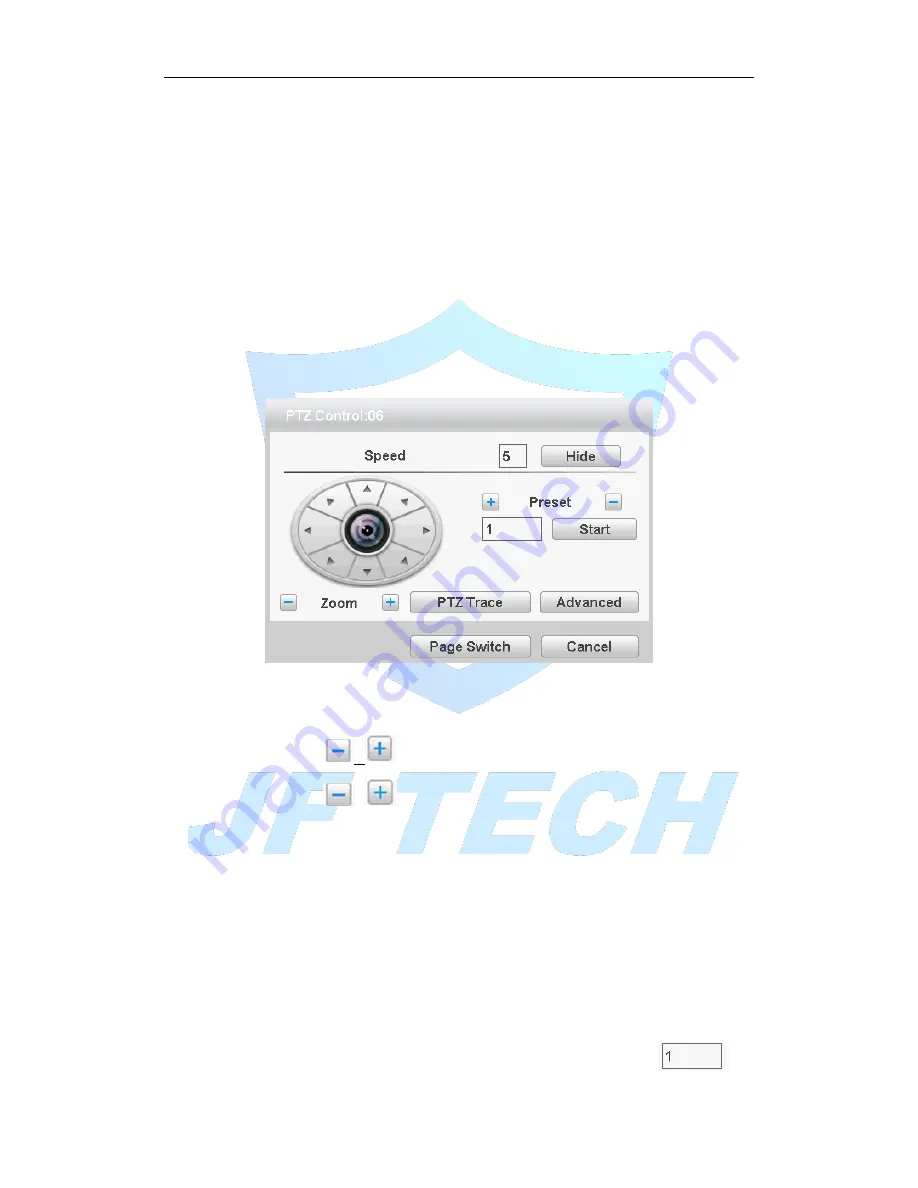
Figure 3.13 PTZ settings 

Speed

Set the PTZ rotation range. Default range: 1 ~ 8. 

Zoom

Click

  /

  button to adjust the zoom multiple of the camera.   

Preset

Click

  /

  button calls the preset points, PTZ automatically turns to 

the setting position. 

Hide

Current interface will be temporarily hidden after click it. 

Direction control

Control the PTZ rotation. 8 directions control is supportive. (4 

directions in Front panel is supportive)   

Advanced

Full-screen show channel image. Left press mouse and control PTZ to 

rotate orientation. Left press mouse and then rotate the mouse to adjust the zoom 

multiple of the camera.   

Page switch

Switch between different pages. 

Preset


1.Increase the preset point 

By the arrow keys to adjust the good Yuntai location

Enter a number in

Summary of Contents for JRC-27F

Page 1: ...Digital Video Recorder Manual Version 1 1 0 JF TECH Co Ltd ...

Page 2: ...dification or repair resulting from the Company is not liable CAUTION 1 Do not make objects fall to vigorously shake the device or equipment and to place the device away from the presence of magnetic interference Avoid installing the surface vibration or vulnerable areas ignore this may damage the device 2 Installed may not be exposed to rain or very humid areas WARNING Precautions to prevent the ...

Page 3: ...DVR do not have the DVR set up in smoke or steam the temperature is too high or there is a lot of dust in the workplace 5 When cleaning use a soft cloth to wipe off the dirt on the housing When cleaning up dirt dry cloth should be cleaned when the dirt is hard to remove use neutral detergent gently wipe clean do not use alkaline detergents If there is sticky dust on the lens use a special lens pap...

Page 4: ...Basic Operations 15 3 1 Turn on 15 3 2 Turn off 15 3 3 System Login 15 3 4 Preview 16 3 5 Desktop shortcut menu 16 4 Main menu 31 4 1 Main menu navigation 31 4 2 Record function 32 4 3 Event function 34 4 4 System settings 40 4 5 Advanced 57 4 6 System Info 67 4 7 Shut down system 70 5 Remote Cloud Operating Instructions 71 5 1 Cloud surveillance 71 6 FAQ and maintenance 74 6 1 FAQ 74 6 2 Maintena...

Page 5: ...ses intelligent buildings intelligent community urban roads airports railway stations and other surveillance applications 1 2 Main Functions Real time surveillance Spot interface analog output interface VGA interface and HDMI interface surveillance function through monitor or display Storage Non working hard disk dormancy processing which is convenient to radiate heat reduce power and extend the l...

Page 6: ...and PTZ control With RS232 interface scalable keyboard connection to the master and connected to the computer serial port for system maintenance and upgrades and matrix control With standard Ethernet interfaces network remote access feature Intelligent operating Mouse action function Fast copy and paste operating for the same setting ...

Page 7: ...in the specification Please check carefully whether the product model on the front panel with foil products you ordered the same model Label affixed to the rear panel has a very important significance for our service work please protect In the company s after sales service when you contact us you will need to provide the model and serial number to order the label Check In addition to checking for ...

Page 8: ... equipment has 15cm 6 inches space around in order to air s circulation 3 From bottom to shelf installation 4 When multiple components install in the frame please take preventive measures to avoid power socket overload 2 4 Front Panel 2 4 1 B series NO Function NO Function NO Function 1 IR 2 Power 3 Record 4 Alarm 5 Menu 6 ESC 7 Direction 8 OK 9 CD ROM 2 4 2 T Series NO Function NO Function NO Fun...

Page 9: ...er indicator 11 IR Receiver 12 Shift 13 Power Switch 14 Next file 15 Play 16 Fast Play 17 Last file 18 Stop 19 USB interface 20 Null 21 Jog wheel 22 Direction 23 CD ROM switch 24 OK 2 5 Rear panel 2 5 1 rear panel interface diagram 16ch as example No Function No Function 1 AUDIO INPUT 7 HDMI 2 ALARM INPUT 8 USB 3 VIDEO INPUT 9 AUDIO INPUT 4 VIDEO OUTPUT 10 RS485 5 AUDIO OUTPUT 11 DC 12V 6 NETWORK ...

Page 10: ... choose the right model If the distance is too far should be based on the specific circumstances the use of twisted pair add video compensation equipment fiber optic transmission and other ways to ensure signal quality Video signal line should avoid strong electromagnetic interference to other equipment and lines especially should avoid high voltage current string into Lugs ensure good contact Sig...

Page 11: ...nd absorbing materials decoration reduce the reflection of the sound improve the acoustic environment 4 Adjust the layout of pickups and speakers but also can reduce the occurrence of howling situations 2 7 Alarm input and output connections Before connecting the device please note the following Note Some Series devices without alarm input and output functions 2 7 1 Alarm Input Alarm input is grou...

Page 12: ...face schematic 1 Alarm input 1 2 3 4 2 Ground 3 RS232 serial interface to send and receive 4 RS485 interface 5 alarm inputs 5 6 7 8 6 Ground 7 alarm output 16 External alarm interface schematic alarm input ground alarm output RS485 RS232 Parameters Meaning G GND R T Send and receive serial interface A B 485 communication interface 2 7 6 Alarm Input Port Description 8 16 channel alarm input input t...

Page 13: ...ant parameters when connecting relay relevant parameters Annex 2 7 8 Alarm output Relay terminal parameters Model JRC 27F Shock material Silver Ratings Resistive load Rated switching capacity 30VDC 2A 125VAC 1A Maximum switching power 125VA 160W Maximum switching voltage 250VAC 220VDC Maximum switching current 1A Insulation between the same polarity Contacts 1000VAC 1 minute between different pola...

Page 14: ...16 external alarm 485 Schematic ...

Page 15: ...oft switch Pressing the power supply switch is called hard switch Illumination 1 Auto resume after power failure If the DVR is shut down abnormally it can automatically backup video and resume previous working status after power failure 2 Replace the hard disk Before replacing the hard disk the power supply switch in the real panel must be turned off 3 Replace the battery Before replacing the batt...

Page 16: ... hour the account will be unlocked automatically For your system security please modify your password after first login 3 4 Preview You can right click mouse to choose the switch between the windows The system date time and channel name are shown in each viewing window The surveillance video and the alarm status are shown in each window 3 5 Desktop shortcut menu In preview mode you can right click...

Page 17: ... you login the system main menu is shown as below Figure 3 3 main menu 3 5 2 Boot wizard Provide fast setup to wizard configuration parameters Including boot wizard two dimensional code and digital channel configuration wizard click Next to enter ...

Page 18: ...e Do not Display select the highlighted expressed after reboot no longer automatically pop up boot wizard Next enter the digital channel configuration wizard interface Cancel to save the settings and exit this screen wizard interface QR Code Figure 3 5 QR code interface Mode selection ...

Page 19: ...gital channels select ad hoc network mode the device will automatically modify the LAN IP address of the front end equipment digital channels and front end devices connect automatically NOTE If you have the front end cannot be modified under the networking mode is recommended since set up a separate LAN Digital Channel Configuration Wizard NOTE After using this function the parameters in the confi...

Page 20: ...ethods respectively NETIP ONVIF ALL 2 Search Search device 3 Add Add device 4 Network Settings The device can be set remotely channel user name password click the Network Settings button you can set the network of the device including IP subnet mask default gateway ONVIF protocol devices cannot make network settings ...

Page 21: ...evices 7 Delete Select the device has been configured click Delete you can delete the device 8 Clear Clear all configured channels 9 encoding settings You can set the front end configured coding 10 Copy to Some information of selected channels can be copied to other channels such as user name password and other device information as shown below ...

Page 22: ...ord can be set in this area 14 Back Return to the previous screen and that is the boot wizard interface 15 completed Add the selected device to the appropriate digital channels and then enable the channel the remaining non selected digital channel is not enabled 16 Exit Return to the preview screen 3 5 3 Playback There are two methods for you to play the video files in the hard disk Through shortc...

Page 23: ...ch mode 7 Channel Selection 8 Date selection 9 Storage device selection Playback control See detail in below chart Button Function Button Function Play Pause Backward play Slow play Fast Rewind Previous frame Next frame Previous file Next file Loop Full screen Edit Start End Clip Clip video backup Table 3 2 Playback control key ...

Page 24: ...g status means it is in recording status You can use desktop shortcut menu to enter the recording control interface Figure 3 11record control Schedule Record according to the configuration Manual Click the all button and the according channel is recording no matter the channel in any state Stop Click the stop button and the according channel stops recording no matter the channel in any state 3 5 5...

Page 25: ... the PTZ parameters 3 The PTZ functions are decided by the PTZ protocols Figure 3 13 PTZ settings Speed Set the PTZ rotation range Default range 1 8 Zoom Click button to adjust the zoom multiple of the camera Preset Click button calls the preset points PTZ automatically turns to the setting position Hide Current interface will be temporarily hidden after click it Direction control Control the PTZ ...

Page 26: ...tings page increase cruise line Can preset point in the input box enter preset point in this page click the Select preset tilt will jump to the preset position interval set point between the cruise when entered the number of seconds after moving to the preset point Set the cruise route steps Input the preset point number then click the add preset point the increase of the preset point will be disp...

Page 27: ...to the previous page complete navigation settings 2 Remove navigation route No delete navigation function 4 The point of the call between the cruise line Input navigation number in the input box in Figure 3 14 and then click between the start key cruise Page Switch In Picture 3 12 click Page Shift button into Picture3 16 setting auxiliary function Figure 3 16 Auxiliary Function Control Intuitive A...

Page 28: ...supports coaxial control function Figure 3 17 coaxial control 3 5 8 Image Color Image color on ONVIF device connection is invalid Set selected channel image parameters when single screen preview of the current channel multi screen cursor to where the channel you can use the desktop shortcut menu enter the interface Image parameters include brightness contrast saturation hue gain horizontal sharpne...

Page 29: ...Figure 3 18 Image color 3 5 9 Output Adjust Adjust TV output area parameters You can use the desktop shortcut menu to choose Output Adjust ...

Page 30: ... Preview in single window four windows eight windows nine windows sixteen windows according to your choice 3 5 12 SPOT This feature is only supported by some models a BNC connector for Spot interface the user can switch SPOT output split screen mode via the context menu After receiving the BNC interface regardless of what to do at the end VGA TV side output device only a preview screen will not di...

Page 31: ... care items video diagnostics Set rules show trail sensitivity minimum travel distance alert mode and set the linkage parameters Arming time alarm output the screen prompts recording PTZ round robin beep EMAIL FTP upload phone reporting System settings General Set the system time date format time format language hard disk full operation the machine ID video format output mode standby time daylight...

Page 32: ...tic reboot the system automatically delete the file time Restore Restore settings Status Normal settings video settings alarm settings network settings network services output mode the serial port settings user management Device information Configure some device hardware information Import export Exporting logs or configure the device to an external device such as U disk connect an external device...

Page 33: ...uration manual on and off Configuration video recording in accordance with general detection and alarm recording type and recording time period set Manual No matter what state the current channel select Manual button the corresponding channel all for normal video Off No matter what state the current channel select the off button the corresponding channel to stop recording week setting common recor...

Page 34: ...ps up you can select the backup video files based on type channel time and other attributes When you click backup then you ll enter next page Clear Clear the displayed file information Added Display file information to meet the set file attributes Backup Format The format of the configuration backup file according to the needs the optional H264 or AVI Start Stop After select the file and backup fo...

Page 35: ...erwise the motion detection function cannot be achieved while the analog channels open as long as the local end manufacturing mobile phenomenon on the line Figure 4 3motion detection Channel Select the number of channels to be set the default one channel to the network camera Enable motion detection alarm enable Sensitivity according to the sensitivity level of the lowest low medium high very high...

Page 36: ... an alarm is triggered the DVR starts recording you need to open detection recording Tour The DVR does not support this feature PTZ Activation When alarming it will turn off the PTZ preset point linkage or linkage between points or cruising Under Mixed mode PTZ is linkage to analog channel corresponding PTZ settings under full digital channels PTZ is linkage to PTZ information corresponding to the...

Page 37: ...e video file or image upload up to a specified location Note Upload FTP need to be set accordingly in the Network Services Buzzer when an alarm occurs the device sends a tick sound long ring Write Log when an alarm occurs the device write a log which you can check on the Info Log 4 3 2 Video blind When the device captured video images by outside influence low light to set the sensitivity parameter...

Page 38: ...d into six kinds namely minimum low medium high very high the highest Setting method refer to chapter 4 3 1 4 3 3 video loss When the device cannot get channel video signal the video loss alarm and the linkage function Note Advanced button is same to the right click Same with motion detection the Mixed mode full analog and digital channels of video loss function differently ...

Page 39: ...urned on if set to normally open you only need to plug the alarm terminal on the local end of the alarm inputs alarm information will be generated but also the corresponding linkage setting function Note Advanced button is same to the right click Figure 4 9 Alarm input Setting method refer to chapter 4 3 1 4 3 5 Abnormality Some current hardware and software analysis and detection equipment and wh...

Page 40: ...screen on the local host screen pop up warning message prompt dialog box Buzzer when an alarm occurs the device sends a tick sound long ring Send Email When an alarm is triggered sends an alarm message to the specified mailbox mailbox settings 4 4 System settings Including General encoding network network services Display PTZ Config Tour 4 4 1 General settings ...

Page 41: ...ll the hard disk is full the measures taken by the camera Overwrite TF card file overwrites the oldest video or capture full time to continue recording and capture Stop TF card when you stop recording and capture video or capture full Video Standard Select the video format supports both PAL and NTSC formats DVR No for this machine with a remote control remote control multiple DVR occasions only ad...

Page 42: ... secondary stream dual stream uses 1080P 720P 960H D1 HD1 CIF QCIF encoding rate of the stream all the way to high definition for local storage support all the way to low bit rate stream QCIF coding for network transmission taking into account local storage and remote network transmission Dual stream network bottlenecks in the existing balance between image quality and transmission quality can bre...

Page 43: ...variable stream Quality set the stream value to change the quality In facilities allow the bigger stream the better the quality Bit Rate According to the code stream flow control and quality varied selection I frame Interval selectable frame interval range 2 12s Video Audio icon when all of the highlighted video file to audio and video composite stream auxiliary stream setting auxiliary stream mai...

Page 44: ...Set the DVR s TCP port the default port is 34567 HTTP port Set the DVR s HTTP port the default port is 80 HS download Network speed downloads Transfer Policy Set the network transmission strategies adaptive quality priority smooth priority network transmission priority four kinds of policy options Adaptive when network bandwidth is small the preview screen automatically jump to sub stream to ensur...

Page 45: ...art the system after saving After starting the DVR will automatically establish a network connection to the PPPoE mode after the success IP IP address will be automatically modify the dynamic WAN IP address obtained Operation After PPPoE dialing successfully view IP IP address on get the current IP address and then uses this IP address to access the device via the client NTP ...

Page 46: ...able set to take effect Server IP Enter installed NTP server PC IP Port The default NTP port 123 the port settings can be based on actual NTP server Update Period the same NTP server check interval the default is 10 minutes Email Set the e mail addresses for DVR sent and received alarm information ...

Page 47: ...essage sender EMAIL address Receiver You can set up to three e mail address separated by a semicolon can outbox the same e mail address Title subject of the message you can set your own IP Filter When choosing the white list the list represents only the IP to connect this DVR A list of supported 64 IP settings When selecting the blacklist represents a list of the IP network cannot be landed this D...

Page 48: ...mic domain name server Domain name Provide the domain name registered by DDNS User name Provide the account registered by DDNS Password Provide the password registered by DDNS When the DDNS is successfully configured and start you can connect the domain name in the IE address column to visit ...

Page 49: ... IP address of the FTP server Port FTP port number field when built the default port 21 User name have permission to log onto the FTP user name Password The user s password Anonymous Anti means chose to be anonymous you do not need to set the user name and password Max File Length Each package upload files maximum length default is 128M DirName file directory to upload files Note The username is e...

Page 50: ...t number corresponding DDNS server service listening port User Name The user name of the device login DDNS server Password The password corresponding to the user name Update Period Equipment and DDNS synchronization interval Note before using the need to build DDNS Server Alarm Server After an alarm it report alarm information to alarm server ...

Page 51: ...ress of alarm server Port port number of the device Alarm report reported anti means reported to the police information to the server Log report Anti means reported to the server log information 3G settings Dial up Internet access through 3G card implement client access device configure the device Figure 4 26 3G settings ...

Page 52: ...the UPNP feature select the Enable set to take effect HTTP Port router for the device is automatically assigned port numbers IE browser the need to add the port number to access TCP Port When the router is automatically assigned port for the device client software monitoring required by the port number Mobile port router for the device is automatically assigned port numbers mobile phone monitoring...

Page 53: ...y match your connected wireless devices Password Wi Fi router s password IP address Set the device s IP address default 192 168 1 9 Subnet Mask Set the device subnet mask default 255 255 255 0 Default Gateway Set the device s default gateway default 192 168 1 1 RTSP Monitoring via cross browser Safari Firefox Google chrome and VLC software These functions only for monitor but cannot control the de...

Page 54: ...ers including time display record status transparency resolution etc Figure 4 31 GUI display Channel Title Click the channel name modify button and enter the channel name menu Modify the channel name The 16 Chinese characters and 25 letters are supportive Time Display means the selective state Display the system data and time in the surveillance window Channel display means the selective state Dis...

Page 55: ...Figure 4 32 RS485 Protocols to select the protocols e g Dahua Address set to the appropriate address the default is 1 Baudrate equipment used to select the appropriate baud rate the default is 115200 Data bits including 5 8 option the default is 8 Stop bits there are two options 1 and 2 the default is 1 Parity points odd parity even parity mark parity space parity the default is none 4 4 7 port se...

Page 56: ...h Data bits Include 5 8 options Stop bits Include 2 options Parity Include odd even mark space default is none 4 4 8 Tour Set the patrol display Mean that the tour mode is enabled You can choose the single view four view six view of single mode tour or hybrid mode tour Figure 4 34 touring settings MD Interval Set the patrol switch interval The set range is 5 120 seconds ...

Page 57: ...verall capability The operation include setup the write read disk read only disk redundant disk hard disk format resume default Choose the hard disk and click the right function button to execute Note Read Write Disk The equipment can write or read data Read only Disk The equipment can read data but cannot write data Redundant Disk Double backup the video files in the write read disk Figure 4 35 S...

Page 58: ...ement include group user The group and user name cannot be the same Each user only belongs to one group Figure 4 36 Account Modify User Modify the user name has been added whether reuse notes group class and permissions Modify Group group name has been added to modify the user group notes and permissions Modify Password modify user login password Note The user who possess the user control purview ...

Page 59: ...ord Add user Set new user name password notes owning group permissions and other information can add up to 64 user names Figure 4 38 Add user Add Group Set the group name new user group notes permissions and other information ...

Page 60: ...roup Delete User delete the selected user the user cannot delete the registry Delete Group delete the selected user group when the group contains a user group cannot be deleted Figure 4 40 delete group 4 5 3 Online user ...

Page 61: ...hen the user will be frozen after connection stopped and will not log in until device reboot Figure 4 41 Online user 4 5 4 Import Export Users can export the log info and the configure file from device to connected flash stick and also can import related configure file from flash stick to settings which greatly bring convenience to the customers ...

Page 62: ...gure 4 42 import export 4 5 5 Upgrade Figure 4 43 Upgrade Upgrade choose USB interface Upgrade file choose the upgrade file 4 5 6 AutoMaintain The user can set the time to auto reboot and auto delete file ...

Page 63: ...restore to the default You can choose the items according to the menu Figure 4 45 Restore 4 5 8 Channel manage Channel management including digital channel channel status and channel mode note under full analog mode there is only channel mode selection ...

Page 64: ...ble then can do related settings Time Sync Tick it means the time of this channel and device is the same Connection Mode can be singe connect or multi ink multi link modes can connect to several devices device will be tour displayed one by one tour interval can be set no less then 10s Delete If the user want to change device select the existing device click delete ...

Page 65: ...s blank Note 1 In Figure 4 47 the protocol search drop down box on the left side there are three namely NETIP ONVIF the whole the user can choose according to demand click search it will search for the corresponding protocol online device 2 Click the Search button the following will show the device as shown in the search to 4 48 the user can double click the device IP connections want according to...

Page 66: ...ution and Connection Status The channel status as 4 2 mode Figure 4 50 Channel Status Remark when the current resolution is over the max resolution that the channel supported then a red X will be shown on the preview image for example Under full digital channel mode Max resolution of channel 3 is D1 if it was connected to a device with resolution over D1 such as 960H Channel mode ...

Page 67: ...ifferent model with different channel mode user can shift the mode freely if necessary 4 6 System Info Display the hard disk information including HDD info code stream statistic log info version info 4 6 1 HDD info Display the hard disk state hard disk type overall capability residual capability the recording time and so on ...

Page 68: ...aged hard disk you must shut down the DVR and take up all the damaged hard disks then install a new one Behind serial number means the current working disk such as 1 If the corresponding disk is damaged the information will show 4 6 2 BPS Display the code stream Kb S and hard disk capability MB H in real time It displays as the wave sketch map Figure 4 53 BPS 4 6 3 LOG ...

Page 69: ...so on Set the time section to look up and click the look up button The log information will display as a list One page is 128 items Press Page up or Page down button to look up and press delete button to clear all the log information Figure 4 54 LOG 4 6 4 Version Display the basic information such as hardware information software version issue date serial number and NAT status and so on Figure 4 5...

Page 70: ...4 7 Shut down system Refer to chapter 3 5 8 ...

Page 71: ...cloud connection status After the device is connected to external networks you can check through main menu System Version If the Nat Status is Connected then it means the device is connecting to the cloud server successfully 5 1 2 Log in cloud server Log http cloud jufenginfo com Pop up the login screen which has login by user and log in by the device two ways the customer can demand their own cho...

Page 72: ... 5 3 device management Figure 5 4Add device Note the user name in Figure 5 5 is the user name of monitoring equipment device password refers to the appropriate device user s password My device The main display device name added to the Device Manager click on the success of the devices connected to the server name you can access to monitor the device ...

Page 73: ...5 surveillance screen 5 1 4 Log in by device Figure 5 6 log in by device Enter the serial number of the device to monitor and verify the code after the direct monitoring equipment Figure 5 7 surveillance screen ...

Page 74: ...t enough Front end video signal instability Adverse heat too much dust the machine is too harsh operating environment DVR hardware failure Q System cannot detect hard disk A Possible reasons are as followed The hard disk power supply line is not connected The cables of the hard disk are damaged The hard disk is damaged The SATA port of main board is damaged Q There are no video outputs in single c...

Page 75: ...s not connected with the video Q The time is wrong A Possible reasons are as followed Setting is wrong The battery is in bad connection or the voltage is too low The oscillation is damaged Q The DVR cannot control the PTZ A Possible reasons are as followed There is something wrong with the frontal PTZ The setting connection or the installation of the PTZ decoder is not correct The connections are ...

Page 76: ...clear Q Network connection is not stable A Possible reasons are as followed Network is not stable IP address is conflicted MAC address is conflicted The net card of the DVR is bad Q There is something wrong with the USB backup or writing a CD A Possible reasons are as followed The rewritable machine and the hard disk are shared the same data lines The data is too much Please stop recording and bac...

Page 77: ...ible reasons are as followed There is no media player There is no DX8 1 software or higher edition There is no DivX503Bundle exe file to play AVI video files The DivX503Bundle exe and ffdshow 2004 1012 exe files must be installed in the windows xp system Q I cannot remember the advanced password or network code in the local menu operation A Please contact the local service or call the HQ service W...

Page 78: ...zen when multi connection and shift devices A Picture come out from digital channel need few seconds shift device means to show new picture so it needs several seconds to buffer 6 2 Maintenance 1 Please brush printed circuit boards connectors fans machine box and so on regularly 2 Please keep the grounding well done to prevent the video or audio signal interfered and the DVR from static or inducti...

Page 79: ......

Page 80: ...ont panel 2 Numeric button Code input number input channel switch 3 Esc Same function as Esc button in the front panel 4 Direction button Same function as direction button in the front panel 5 Record control Control the record 6 Record mode Same function as Record mode 7 ADD Input the number of DVR to control it 8 FN Assistant function ...

Page 81: ...hannel to make it full screen display double click again to resume the multi window display Left click Choose the according function in the menu Right click Pop desktop shortcut menu in preview state Current shortcut menu in the menu Press middle button Add or subtract number in the number setting Switch the items in the combo box Page up or down in the list Move mouse Choose the widget or move th...

Page 82: ...hour capability in an hour M hour The recording time formula is Recording time hour overall capability M Capability in an hour M hour channel number The DVR introduces the H 264 compression technology Its dynamic range is very large so the hard disk capability calculation is based on the estimation values of each channel creating files in an hour Example For one piece 500G HDD real time CIF for re...

Reviews: