background image


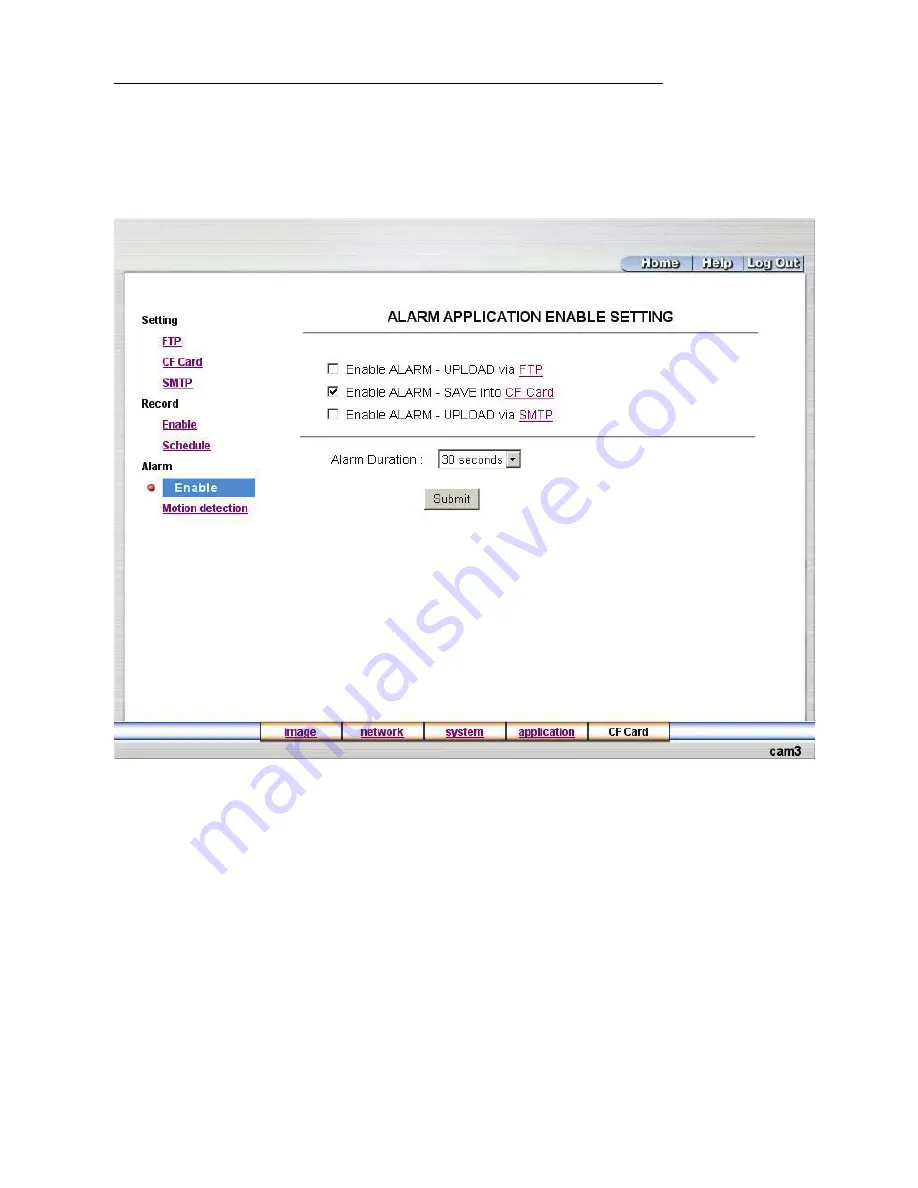
Change the Application Setting — ALARM APPLICATION ENABLE SETTING. 

Please follow the steps below to change the setting via the network if and as necessary. 

1. Click 

the 

Enable

 button on the left side of the record to enter the “ALARM APPLICATION 

ENABLE SETTING” page. 


2. 

Click “Enable ALARM – UPLOAD via FTP” to checkmark the attached box and activate the 

function. 

3. 

Click “Enable ALARM – SAVE into CF Card” to checkmark the attached box and activate 

the function. 

4. 

Click “Enable ALARM – UPLOAD via SMTP” to checkmark the attached box and activate 

the function. 

5. 

Enter the "Alarm Duration" you have chosen. 

6. Click 

the 

Submit

 button to submit the new setting of the recording. 

7. Click 

the 

Home

 button to return to the home page. 


45

Summary of Contents for JCK-32CL

Page 1: ...Before trying to connect or operate this product please read this manual completely INSTALLATION OPERATION MANUAL LAN CAMERA...

Page 2: ......

Page 3: ...0 3 2 CONNECTING WITH A DVR 10 3 3 CONNECTING WITH A MULTIPLEXER 11 3 4 UPDATING SYSTEM SOFTWARE 11 3 5 LAN CAMERA CF CARD TROUBLESHOOTING 12 4 Network Configuration 14 4 1 CABLE CONNECTIONS 14 4 1 1...

Page 4: ...Setting 26 5 1 4 Change the System Setting 35 5 1 5 Change the Application Setting 40 5 1 6 Change the CF Card Setting 48 5 1 7 PPPoE DDNS 49 5 2 THE LAN CAMERA VIEWER 52 5 2 1 Introduction to Network...

Page 5: ...s may expose you to dangerous voltage or other hazards Please refer all servicing to qualified professional personnel service personnel Do not use liquid cleaners or aerosols for cleaning To prevent f...

Page 6: ...re your house factory school public space and so forth You can set up different size frames and image quality categories in accordance with your requirements Different settings have different picture...

Page 7: ...tion BLC Electronic shutter speeds NTSC 1 50 1 10000 sec PAL 1 60 1 10000sec The sensitivity is 1 2 000 000 Lux Image compression MJPEG There are 5 levels of image quality the user can select from Low...

Page 8: ...f users account included under these 3 levels is ten Time Lapse and Real Time recording are featured options The device is capable of working with various known multiplexers and quad processors RS 232...

Page 9: ...evice 3 VIDEO OUT Connector The connector provides the unit s composite video signals to a monitor 4 AUDIO OUT This provides the unit s audio signal to a speaker 5 ALARM I O This is a 4 PIN D SUB conn...

Page 10: ...ct this to external devices such as buzzers or lights 5V 20mA 0V Active 2 GND Ground contact 3 ALARM IN INPUT This is an alarm input that can be programmed in the menu system to active low 5V 20mA 0V...

Page 11: ...IP Switch 1 AES Auto electric shutter 2 DC IRIS Use auto iris DC drive 3 DHCP Turn On Turn Off the DHCP protocol The switch points upwards the device can change the setup of network function enable di...

Page 12: ...ction between the LAN CAMERA and another device If there is no such connection the LAN CAMERA factory default Static IP address will not appear on the monitor screen 3 1 CONNECTING WITH AN NVR Use a c...

Page 13: ...directory already exists move to Step3 3 Copy the file of UPDATE BIN to the LANCAM directory 4 If the LANCAM is running please power it off first 5 Insert the CF CARD into the LANCAM in a face down po...

Page 14: ...our technical support 5 In Step10 if the CF Card is not removed and the LANCAM does not go online as well the update process will repeat again after rebooting the LANCAM 6 Make sure that the CF Card i...

Page 15: ...ta through the web page of cfget htm If the data cannot be read through the networks please read it by a PC instead and check out the data stored in the LANCAM directory and please contact your techni...

Page 16: ...tion for connections Physical specifications of RJ 45 cable for Ethernet Wire Type Cat 5 Connector Type RJ 45 Max Cable Length 30 m Hub Wiring Configuration Straight Through PC Wiring Configuration Cr...

Page 17: ...or connecting with a LAN Hub is shown below RJ 45 LAN CAMERA TO PC NETWORK CARD uplink 4 1 3 Connect to WAN INTERNET The RJ 45 PIN configuration for connecting to a WAN is the same as connecting to a...

Page 18: ...MASK and GATEWAY The following is a sample setting IP 192 168 1 X MASK 255 255 255 0 GATEWAY 0 0 0 0 NOTE When only one unit of the LAN CAMERA is connected to a computer or LAN you can freely assign a...

Page 19: ...e the first three sets of numbers of the LAN CAMERA IP address must be the same as the network address If the connected network is identified as Class B the first two sets of numbers of the LAN CAMERA...

Page 20: ...llow the instructions below to install the TCP IP communication program into your computer Click the Start menu from your computer and point to the Settings Control panel Click the Network icon twice...

Page 21: ...ork components list If the TCP IP is included please process step 5 If it is not included please follow step 4 to install the TCP IP 4 4 TCP IP Installation During the installation you will be request...

Page 22: ...P server please select Obtain an IP address automatically Any assigned IP address for the connected LAN CAMERAs must be in the same class type as the server If there is no DHCP server please select sp...

Page 23: ...ns below to ensure whether you have established the connection successfully Click Start Programs MS DOS Prompt Type in ping 192 168 1 168 then Enter See the sample screen below This IP is the LAN CAME...

Page 24: ...ully established Please re check all the hardware and software installation by repeating steps 1 to 5 If you still can t establish the connection after rechecking please contact your dealer If you rec...

Page 25: ...ows 95 98 NT ME 2000 and XP 4 MB VGA card capable of 24 bit true color display 20 MB free hard disk space for software installation 10 100 Base TX network for LAN operation The Microsoft Internet Expl...

Page 26: ...er you click the page headlined Enter Network Password will appear 5 Type in the User Name and Password in the appropriate spaces 6 Click the OK button to set your entries and automatically exit the p...

Page 27: ...at the bottom of the home page for further setting Click the image button to enter the image setting page Click the network button to enter the network setting page Click the system button to enter t...

Page 28: ...ightness Hue Saturation Sharpness and Viewer Type if and as necessary 3 Click the Submit button to submit the new image setting 4 Click the Home button to return to the home page while the new image s...

Page 29: ...ou want selecting out of an available range from 0 to 255 Brightness Enter your desired quality of image brightness from a spectrum of 0 to 255 HUE Enter the hue value in the given space 0 to 255 Satu...

Page 30: ...wn an IP address to be identified on the network Netmask Fill in the 4 byte Subnet Mask in the required blank spaces usually any numbers between 0 and 255 It is used to identify the subnet where the L...

Page 31: ...it the new FTP setting of the recording 4 Click the Home button to return to the home page Description of function keys FTP IP Address Enter the FTP server DOMAIN NAME in the appropriate blank spaces...

Page 32: ...SMTP server and set the recipient s e mail address when and as necessary 3 Click the Submit button to submit the new SMTP setting 4 Click the Home button to return to the home page Description of fun...

Page 33: ...essary 3 Click the Submit button to submit the new SMTP setting 4 Click the Home button to return to the home page Description of function keys SNTP Server Enter the SNTP server DOMAIN NAME in the bla...

Page 34: ...pe to open the list of three DDNS modes to choose from DynDNS hn and adsldns Click the Apply button and connect their websites automatically and visit them Type in your dynamic IP Address and Email Ad...

Page 35: ...n and connect this website automatically and enter it Type in your dynamic IP Address and Email Address If they are accepted by the Website you will get an Email containing your DDNS Account and DDNS...

Page 36: ...e 2 Click the PPPoE mode to activate the function 3 Type in the PPPoE Account and the PPPoE Password 4 Click the Submit button to submit the new setting 5 Click the Home button to return to the home p...

Page 37: ...Synchronize with computer time and Synchronize with NTP server 3 Click the Submit button to submit the new Date and Time setting 4 Click the Home button to return to the home page Description of funct...

Page 38: ...s data if and as necessary 3 Click the Submit button to submit the new user s setting 4 Click the Home button to return to the home page Description of function keys User List The list shows the regi...

Page 39: ...rk Digital Input ON or OFF and the Digital Output ON or OFF Click your choices to enable 3 Click the Submit button to submit the new user s setting 4 Click the Home button to return to the home page D...

Page 40: ...Home button to return to the home page NOTE This setting is for turning the audio mechanism of the Camera on off automatically Live audio service is not provided by the Web browser Description of func...

Page 41: ...page to view an event when necessary The three buttons are titled First Page Previous 20 and Next 20 Description of function keys First Page Displays the first page Previous 20 Displays the previous...

Page 42: ...ETTING page default 2 For storage setting type in the respective required numbers of images you wish to set in the Pre Alarm Memory Buffer and the Alarm Memory Buffer in their corresponding blank spac...

Page 43: ...t and click Submit to set it 3 If it s JPEG you want fill in the Max JPEG Numbers entry 4 If AVI is your choice enter its recording rate and duration in seconds and click Submit for their setting Desc...

Page 44: ...ton on the left side to enter the SMTP APPLICATION SETTING page 2 Enter the attached file number as and when necessary The maximum number which can be used is 8 3 Click the Submit button to submit the...

Page 45: ...OAD via FTP to checkmark the attached box and activate the function 3 Click Enable RECORD SAVE into CF Card to checkmark the attached box and activate the function 4 Click the Submit button to submit...

Page 46: ...tton to submit the new schedule setting 4 Click the Remove All Schedule button to clear out all the data of the schedule setting Description of function keys Schedule Check uncheck the first seven box...

Page 47: ...G page 2 Click Enable ALARM UPLOAD via FTP to checkmark the attached box and activate the function 3 Click Enable ALARM SAVE into CF Card to checkmark the attached box and activate the function 4 Clic...

Page 48: ...SMTP Activates or deactivates the alalrm recording upload to the SMTP Alarm Duration Predetermines the length of the alarm Change the Application Setting ALARM MOTION DETECTION Please follow the step...

Page 49: ...recording 7 Click the Home button to return to the home page Description of function keys The targeted zone Click and drag the mouse across the targeted zone to draw a red rectangle on the image Detec...

Page 50: ...below to change the setting via the network if and as necessary 1 Click the CF Card button at the bottom of the home page to enter the page containing the FILELIST of MEMORY CARD The page comes in two...

Page 51: ...properties Type in the IP address in a four part formula for example 192 168 1 101 the first three parts must be identical to the above numbers only the last part can be changed to your own number wh...

Page 52: ...ur password again Click Create Account if successful the words Account Created will appear if false or flawed or identical to someone else s User name the page will remain unchanged you must now chang...

Page 53: ...e in DDNS Account for example abc123 Enter the DNS Password for example 7777 Submit The settings are now accomplished Close the IE browser 3 Open the IE browser again Type in the Website address you j...

Page 54: ...are ready to view images from a desktop you need to have your LAN CAMERA networked by obtaining a 10 100 base TX Ethernet data cable Standard RJ 45 to connect the LAN CAMERA to your LAN WAN Now enter...

Page 55: ...w the on screen instructions to proceed with the rest of the installation procedure as they appear 4 After the installation is complete pop up the START menu from your computer and point to Programs L...

Page 56: ...ton and enter the Console page of the Network Viewer both the user name and password must be entered correctly Click the Cancel button and exit the login of the Network Viewer View the LANCAMERA video...

Page 57: ...the bottom of the page to access the list of device types Click the device of your choice and click Select at the bottom of the page to access the Add Device Wizard page again Or b type in the IP Add...

Page 58: ...blish the connection between the device and the computer Click the channel to begin viewing images with this camera from the Device List NOTE Upon connection if there s a failure to connect a message...

Page 59: ...icon to enter the single device mode window See the sample screen below This window on the right side of the Console page displays the connected device that has been arranged when you established the...

Page 60: ...Change the Settings Via the Network Follow the instructions below to reconfigure the settings via the network A B 58...

Page 61: ...the Video Resource of the Image page 1 When in the Device List select a desired channel to enable the button and click the button to enter the Device Setting page See the sample screen as in A above 2...

Page 62: ...ouse across a targeted zone to draw a red rectangle on the image coordinates provided above 5 Click your required level of Sensitivity at the bottom of the page 6 Click the Apply button to save the mo...

Page 63: ...The quad modes and the single channel Click the fourth button from the left above the window to alternately turn on the single channel and the quad modes 61...

Page 64: ...Change the PC SYSTEM SETTING Follow the instructions below to reconfigure the System Setup Alarm Setup and Schedule Setup A B C 62...

Page 65: ...ormat if and as necessary 4 Set the disk full to over write to in order enable the Disk Full Over Write setting area 5 Charge the image file path if and as necessary 6 Click the Apply tag to proceed S...

Page 66: ...View the LIVE MONITOR Follow the instructions below to open the Network Viewer Monitor window 64...

Page 67: ...n to the Network Viewer Console page Viewer Mode offers a choice between Continue nonstop surveillance and Push viewing a particular event Alarm Setting offers three choices Enables disables schedulin...

Page 68: ...Network Viewer Player Click the button to view the Network Viewer Player window 66...

Page 69: ...h are faster than the recorded speed REV Click to play a recorded video in the reverse direction at speeds which are faster than the recorded speed Click to return to the Network Viewer Monitor mode R...

Page 70: ...starting and ending points of an image display when user wants to transfer a file JPEG Archives images in the JPEG format to save a single picture in every file AVI Archives images in the AVI format...

Page 71: ...lick Set to insert the date and time of the time period viewed 3 Select either AVI or JPEG to export a file of either format and select the file path via which to send viewed records for storage 4 If...

Page 72: ...Viewer will not display the image and instead will send a warning message of Not Correct Image right away Close this message to enable you to see the image now 1 Pop up the START menu from your comput...

Page 73: ...Compression MJPEG Picture size 4 64 KB Video fine tune Brightness HUE Saturation Backlight Sharpness Watermarker Digital Signature Communication Port RS 232 RS 485 Network Interface Ethernet RJ 45Wire...

Page 74: ...lient PC System requirement Windows Browser IE 5 x 6 x Camera setup Username IP PROXY Password Time Date Motion Alarm Multi camera link 16 camera Viewer 1 4 SPLIT PT control Support Save file format B...

Page 75: ...device 2 Select the desired device from the Device List 3 Click the desired device to show the window while the LANCAMERA information acts to display the desired changes instantly 4 Do you want to ex...

Page 76: ...as required in the Free IP Address Gateway Address and NET Mask Follow each insertion you make by typing in the Login Name and Password and click UPDATE to send your alterations to the LAN Camera 6 Au...

Page 77: ...n the left 8 To change any IP address type in the new address in the Free IP Address box on the right as well as the device Login Name and Password in their respective blanks at bottom left then click...

Page 78: ...erating The green light indicates the unit is activating The red light warns the CF card cannot be removed If the CF card is withdrawn in this mode the card will break 3 I ve set the function of Motio...

Reviews: