


12
8.6
Coolant pump (optional)
The coolant system (not provided) should be filled
with 2 gallons of a cutting coolant. Fill by pouring
coolant into base of machine. Add coolant in the
same manner when coolant is low. To drain coolant,
remove hex cap screw located on lower backside of
base. Follow all coolant manufacturer’s instructions
for safety, mixing and disposal.
Make sure drain hose has good, tight connection
into table and that coolant flows into base.
Make sure hose leaving pump and entering ball
valve has good, tight connections.
The flexible nozzle enables user to adjust coolant
for each job. One ball valve controls coolant flow to
nozzle.
9.0
Operation
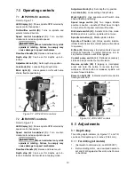
9.1
Operating precautions
The following operating and safety precautions must
be observed in order to avoid harm to operator or
damage to drill press.
1. Head assembly must be locked to column so
the thrust produced by drilling will not force the
head assembly up the column.
2. Work table must be locked to column so it will
not be forced down the column.
3. Belts should be properly tensioned.
4. Do NOT start to drill workpiece until making
certain workpiece is held down securely.
5.
Make sure drive motor is running BEFORE
turning speed control handwheel in either
direction.
6. Point of operation protection is required for
maximum safety. This remains the
responsibility of the user/purchaser since
conditions differ between jobs.
7. Make sure tool is secured in the spindle or
chuck before attempting to use the drill press.
8. Make sure spindle taper is clean and free of
burrs, scoring, and galling to assure maximum
gripping.
9. Lock quill in position when using any side-
loaded tool.
9.2
Drilling recommendations
9.2.1
Drilling speeds
The speed of a drill is usually measured in terms of
the rate at which the outer periphery of the tool
moves in relation to the work being drilled. The
common term for this is Surface Feet per Minute
(SFM). The relationship of SFM is expressed in the
following formulas:
SFM = 0.26 X RPM X Drill Diameter (in inches)
RPM = 3.8 x ________SFM__________
Drill diameter (in inches)
In general, the higher the speed the shorter the drill
life. Operating at the low end of the speed range for
a particular material will result in longer life. The
most efficient speed for drill operation depends
upon many variables:
1.
Composition and hardness of material.
2.
Depth of hole.
3.
Efficiency of cutting fluid.
4.
Type and condition of drilling machine.
5.
Desired quality of hole.
6.
Difficulty of set-up.
9.2.2
Drilling feed
The feed of a drill is governed by size of tool and the
material drilled. Because feed rate partially
determines rate of production and also is a factor in
tool life, it should be chosen carefully for each job.
In general, the most effective feeds will be found in
the following ranges:
Diameter of Drill
(inches)
Feed per Revolution
(inches)
Under 1/8
0.001 to 0.002
1/8 to 1/4
0.002 to 0.004
1/4 to 1/2
0.004 to 0.007
1/2 to 5/8
0.007 to 0.015
Table 3
9.2.3
Speeds for high speed steel drills
Material
Speed (SFPM)
Alloy Steel — 300 to 400 Brinell
20-30
Stainless Steel
30-40
Automotive Steel Forgings
40-50
Tool Steel, 1.2C
50-60
Steel, .4C to .5C
70-80
Mild Machinery Steel, .2C to .3C
80-110
Hard Chilled Cast Iron
30-40
Medium Hard Cast Iron
70-100
Soft Cast Iron
100-150
Malleable Iron
80-90
High Nickel Steel or Monel
40-50
High Tensile Bronze
70-150
Ordinary Brass and Bronze
200-300
Aluminum and its Alloys
200-300
Magnesium and its Alloys
250-400
Slate, Marble, and Stone
15-25
Plastics and similar materials
(Bakelite)
100-150
Wood
300-400
Titanium Alloys
10-25
Titanium Alloy Sheet
50–60
Note: In cases where carbon steel drills are applicable, the
drill should be run at speeds of 40 to 50 percent of those
given above.
Table 4
Summary of Contents for JDP-20VS-3
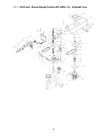
Page 16: ...16 13 1 1 Drill Head Manual Speed Control JDP 20VS 1 3 Exploded View...
Page 19: ...19 13 2 1 Drill Head Two Speed Control JDP20VST Exploded View...
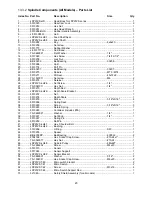
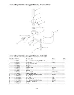
Page 22: ...22 13 3 1 Spindle Components All Models Exploded View...
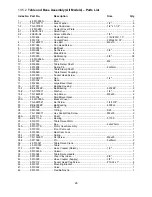
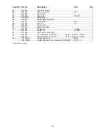
Page 25: ...25 13 5 1 Table and Base Assembly All Models Exploded View...
Page 29: ...29 14 2 JDP20VST wiring diagram...
Page 31: ...31 This page intentionally left blank...
Page 32: ...32 427 New Sanford Road LaVergne Tennessee 37086 Phone 800 274 6848 www jettools com...


