


3
17. Keep hands in sight and clear of all moving
parts and cutting surfaces.
18. All visitors should be kept at a safe distance
from the work area. Make workshop completely
safe by using padlocks, master switches, or by
removing starter keys.
19. Know the tool you are using — its application,
limitations, and potential hazards.
20. The installer shall follow local regulations and
National Electrical Code, ANSI/NFPA 70
installation requirements.
21. Clamp workpiece or brace against column to
prevent rotation.
22.
MAKE WORKSHOP KID PROOF with
padlocks, master switches, or by removing
starter keys.
23. NEVER STAND ON TOOL Serious injury could
occur if the tool is tipped or if the cutting tool is
unintentionally contacted.
24. CHECK DAMAGED PARTS. Before further use
of the too., a guard or other part that is damaged
should be carefully checked to determine that it
will operate properly and perform its intended
function – check for alignment of moving parts,
binding of moving parts, breakage of parts,
mounting, and any other conditions that may
affect its operation. A guard or other part that is
damaged should be properly repaired or
replaced.
25. Grounding instruction: This tool should be
connected to a grounded metal permanent
wiring system; or to a system having an
equipment-grounding conductor.
Familiarize yourself with the following safety notices used in this manual:
This means that if precautions are not heeded, it may result in minor injury and/or
possible machine damage.
This means that if precautions are not heeded, it may result in serious or even fatal
injury.
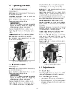
1.2
General electrical cautions
This drill press should be grounded in accordance with the National Electrical Code and local codes and
ordinances. This work should be done by a qualified electrician. The saw must be grounded to protect the user
from electrical shock.
Wire sizes
Caution:
For circuits which are far away from the electrical service box, the wire size must be increased in order
to deliver ample voltage to the motor. To minimize power losses and to prevent motor overheating and burnout,
the use of wire sizes for branch circuits or electrical extension cords according to Table 2
(sect. 6.4)
is
recommended.
WARNING:
This product can expose you to
chemicals including lead and cadmium which
are known to the State of California to cause
cancer and birth defects or other reproductive
harm, and phthalates which are known to the
State of California to cause birth defects or other
reproductive harm. For more information go to
http://www.p65warnings.ca.gov.
WARNING:
Some dust, fumes and gases
created by power sanding, sawing, grinding,
drilling, welding and other construction activities
contain chemicals known to the State of
California to cause cancer and birth defects or
other reproductive harm. Some examples of
these chemicals are:
•
lead from lead based paint
•
crystalline silica from bricks, cement and
other masonry products
•
arsenic and chromium from chemically
treated lumber
Your risk of exposure varies, depending on how
often you do this type of work. To reduce your
exposure to these chemicals, work in a well-
ventilated area and work with approved safety
equipment, such as dust masks that are
specifically designed to filter out microscopic
particles. For more information go to
http://www.p65warnings.ca.gov/ and http://www.
p65warnings.ca.gov/wood.
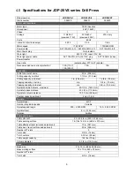
Summary of Contents for JDP-20VS-3
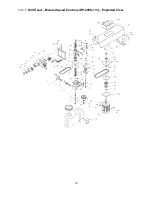
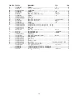
Page 16: ...16 13 1 1 Drill Head Manual Speed Control JDP 20VS 1 3 Exploded View...
Page 19: ...19 13 2 1 Drill Head Two Speed Control JDP20VST Exploded View...
Page 22: ...22 13 3 1 Spindle Components All Models Exploded View...
Page 25: ...25 13 5 1 Table and Base Assembly All Models Exploded View...
Page 29: ...29 14 2 JDP20VST wiring diagram...
Page 31: ...31 This page intentionally left blank...
Page 32: ...32 427 New Sanford Road LaVergne Tennessee 37086 Phone 800 274 6848 www jettools com...


