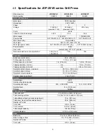
background image

11 


3.  Set depth block to zero by turning knurled knob 

(E

1

). Then adjust block to desired depth of hole, 

and secure setting with knob (E

2

).  

4.  Start motor and drill hole until travel is 

restrained by indicator block. 

8.1.2

  For tapping (JDP-20VST only) 

1.  Set depth stop in same manner as above. 

2.  Set tapping mode (H). 

3.  When quill is advanced using downfeed handle 

(D), upper limit switch will be released for 
tapping. When lower limit switch is triggered, 
spindle will reverse rotation direction. When 
spindle is returned to highest position, it will 
resume forward rotation. 

NOTE: When tapping mode is off, limit switches are 
deactivated and do not affect spindle rotation. 
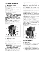
8.2

  Table adjustment  

The table can be raised or lowered to accommodate 
workpiece height. Place hand crank on shaft (A, 
Figure 8-1) and turn counterclockwise to loosen 
table lock. Then use hand crank on shaft B or C to 
raise or lower table. Lock table in position using 
shaft A. 

If drill press base is to be used for securing 
workpiece, loosen table (A) and swing it around 
column and out of the way. Retighten table. 


Figure 8-1:  table adjustments 

8.3

  Tool installation and removal 

1.  Disconnect machine from power source. 

2.  Thoroughly clean inside of spindle with a soft 

dry cloth. Also clean any taper or arbor to be 
used in the spindle. If these are not kept clean, 
taper or arbor will not “seat” properly in spindle 
and may drop out unexpectedly.  

3.  Place protective piece of scrap wood on table. 

4.  Raise table to approximately 8-to-10 inches 

below spindle. 

5.  Insert MT-4 tool into spindle. 

6.  Lower spindle using downfeed handle, and seat 

tool against the wood. 

7.  If installing a drill chuck, retract the jaws then 

use rubber mallet (or steel face hammer against 
a block of wood) to sharply tap bottom of chuck 
two or three times to seat it. NOTE: Never use 
a steel face hammer directly against the chuck. 

To remove a tool: 

1.  Disconnect machine from power source. 

2.  Lower spindle to expose slots in spindle wall. 

3.  Insert drift key into spindle slots and tap gently 

until drill bit or chuck arbor loosens. Hold tool 
with one hand (use glove or rag if needed) while 
tapping to prevent tool from falling and being 
damaged. 

8.4

  Speed pickup adjustment 

Speed pickup has been set correctly by the 
manufacturer. If the speed readout display should 
lose accuracy, adjustment can be made as follows. 
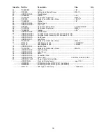
Refer to index numbers on exploded view, 

sect. 

13.3.1. 

1.  Loosen screws securing speed pickup (ref. #50) 

to plate (#51). 

2.  Adjust speed pickup gap to approximately 1/8-

inch. Retighten screws. 

3.  Operate drill press to verify that speed readout 

is operating correctly. 

8.5

  Spindle return spring adjustment 

The spindle return is preset by the manufacturer and 
should not need adjustment. If future attention is 
ever required, proceed as follows:   

1.  Do NOT remove spring cap (D, Figure 8-2).   

2.  Loosen knob (E) just enough to rotate spring 

cap past notch (F). 

3.  Rotate spring cap clockwise to decrease spring 

tension. Rotate spring cap counter-clockwise to 
increase spring tension. 

4. Re-tighten 

knob 

(E). 


Figure 8-2:  return spring adjustment 


Summary of Contents for JDP-20VS-3

Page 1: ...Manual 20 Variable Speed Drill Press Models JDP 20VS 1 JDP 20VS 3 JDP 20VST JDP 20VST JDP 20VS JET 427 New Sanford Road LaVergne Tennessee 37086 Part No M 354230 Ph 800 274 6848 Edition 5 10 2018 www...

Page 2: ...not comply with ANSI Z87 1 specifications could result in severe injury from breakage of eye protection 2 Wear proper apparel No loose clothing or jewelry which can get caught in moving parts Rubber...

Page 3: ...y 1 2 General electrical cautions This drill press should be grounded in accordance with the National Electrical Code and local codes and ordinances This work should be done by a qualified electrician...

Page 4: ...lds complying with ANSI Z87 1 specifications Use of eye wear which does not comply with ANSI Z87 1 specifications could result in severe injury from breakage of eye protection B Figure 1 1 7 When dril...

Page 5: ...ation 12 9 1 Operating precautions 12 9 2 Drilling recommendations 12 10 0 User maintenance 13 10 1 Drive belt replacement 13 10 2 Motor replacement 13 10 3 Lubrication 13 10 4 Additional servicing 13...

Page 6: ...Drilling capacity mild steel 1 in 25 4 mm 1 3 8 in 35 mm Tapping capacity cast iron n a 3 4 in 19 mm Tapping capacity mild steel n a 5 8 in 15 9 mm Spindle to table distance maximum 30 1 4 in 768 4 m...

Page 7: ...des 2 The specified values are emission levels and are not necessarily to be seen as safe operating levels As workplace conditions vary this information is intended to allow the user to make a better...

Page 8: ...ft key 1 Operating and parts manual 1 Product registration card 5 2 Securing base It is strongly recommended that drill press be secured to floor The drill press base has four mounting slots see Figur...

Page 9: ...is available for the operator During hard wiring of the machine make sure the fuses have been removed or the breakers have been tripped in the circuit to which the drill press will be connected ALWAY...

Page 10: ...th stop position Lock knob E2 Locks setting of depth stop Work light F Has separate on off switch atop shade flexible positioning Speed range switch G Two ranges Middle position is neutral spindle off...

Page 11: ...of scrap wood on table 4 Raise table to approximately 8 to 10 inches below spindle 5 Insert MT 4 tool into spindle 6 Lower spindle using downfeed handle and seat tool against the wood 7 If installing...

Page 12: ...at which the outer periphery of the tool moves in relation to the work being drilled The common term for this is Surface Feet per Minute SFM The relationship of SFM is expressed in the following formu...

Page 13: ...ower to drill press to avoid possibility of inadvertent operation and exposure to potentially lethal voltage levels 1 Remove drive belt sect 10 1 2 Disconnect electrical wiring from motor junction box...

Page 14: ...locations and drill holes Refer to Figure 11 1 Note Mount components near the lower edge of the spindle casting DO NOT mount components above the line shown in Figure 11 1 5 Install power switch and...

Page 15: ...No or improper cutting fluid or coolant being used Use cutting fluid or change to proper fluid or coolant for material being drilled Improperly ground drill bit Check for proper angles and reliefs Reg...

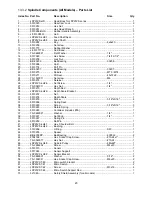
Page 16: ...16 13 1 1 Drill Head Manual Speed Control JDP 20VS 1 3 Exploded View...

Page 17: ...ring 6302zz 2 29 F006077 C Ring Internal Hole R 42 1 30 JDP20VS TH30 Speed Change Bracket 1 30 1 JDP20VS TH30 1 Support Rod 1 30 2 6286478 C Ring External Shaft S 12 2 31 JDP20VS TH31 Speed Change Lev...

Page 18: ...bly 1PH includes 74 78 1 JDP20VS TH69 3 Fwd Rev Switch Assembly 3PH includes 74 78 1 70 JDP20VS TH70 Cap Screw 2 71 JDP20VS TH71 Face Plate 1 72 TS 1533032 Phillips Pan Hd Machine Screw M5x10 4 73 551...

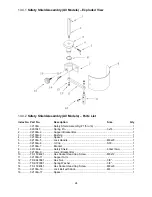
Page 19: ...19 13 2 1 Drill Head Two Speed Control JDP20VST Exploded View...

Page 20: ...302zz 2 29 F006077 C Ring Internal Hole R 42 1 30 JDP20VS TH30 Speed Change Bracket 1 30 1 JDP20VS TH30 1 Support Rod 1 30 2 6286478 C Ring External Shaft S 12 2 31 JDP20VS TH31 Speed Change Lever 1 3...

Page 21: ...Switch 1 104 JDP20VST TH104 Selection Switch D T 1 105 JDP20VST TH105 Emergency Stop Switch 1 106 JDP20VST TH106 Stop Switch 1 107 JDP20VST TH107 Start Switch 1 108 JDP20VST TH108 Electric Box 1 109 J...

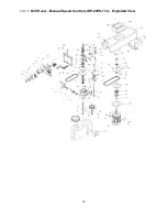
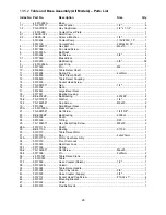
Page 22: ...22 13 3 1 Spindle Components All Models Exploded View...

Page 23: ...x Nut 1 4 1 28 5510273 Depth Rod 1 29 JDP20VS LH29 Depth Scale Bracket 1 30 5510272 Nut 1 31 5510278 Depth Scale 1 32 5510279 Screw 3 16 x5 16 4 33 5510266 Spring Seat 1 34 5510265 Screw 3 16 x5 16 3...

Page 24: ...cket Bar 1 3 32106A 3 Bushing 1 4 32106A 4 Spacer 1 5 32106A 5 Lock Handle M6x20 1 6 32106A 6 C Clip S30 1 7 32106A 7 Bracket 1 8 32106A 8 Safety Shield 530x210mm 1 9 32106A 9 Lower Bracket Bar 1 10 T...

Page 25: ...25 13 5 1 Table and Base Assembly All Models Exploded View...

Page 26: ...Large Bevel Gear 1 18 5517391 Bearing Housing 1 18 1 BB 6202ZZ Ball Bearing 6202ZZ 2 18 2 TS 0720071 Washer 1 4 2 18 3 TS 1482041 Cap Screw M6x20 2 19 5510304 Small Bevel Gear 2 20A J 5510305A Bracket...

Page 27: ...Flat Washer 10 2 58 5517488 Hex Nut 1 2 1 59 5517489 Power Cord 1 60 5517490 Switch Assembly 1 61 5517491 Pump Cord 1 Phase 1 5517492 Pump Cord 3 Phase 1 62 5517493 Hose Clamp Rad Type 2 65 5512104 Co...

Page 28: ...28 14 0 Electrical connections Similar diagrams are affixed inside electrical cabinet door In case of discrepancy diagrams on machine take precedence 14 1 JDP 20VS 1 and JDP 20VS 3 wiring diagram...

Page 29: ...29 14 2 JDP20VST wiring diagram...

Page 30: ...tional action needed JET has Authorized Service Centers located throughout the United States For the name of an Authorized Service Center in your area call 1 800 274 6846 or use the Service Center Loc...

Page 31: ...31 This page intentionally left blank...

Page 32: ...32 427 New Sanford Road LaVergne Tennessee 37086 Phone 800 274 6848 www jettools com...

Reviews: