January, 2009
11
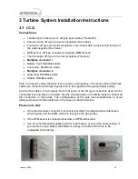
I.C.S. Main Unit
Because the
I.C.S.
is an electronic piece of equipment, the installation in the model aircraft is
similar to that of the radio receiver. It has to be in an accessible location within the airframe,
with limited vibration and far from the heat of the engine. Also because the pump motor uses
DC power, that can produce sparks in the collector when operating, it is highly recommended
that the installation of all electrical equipment be done as far as possible from the R/C
receiver. Keep the power cables at the minimum possible length and avoid installing the
antenna near them.
3.2 Pump/Starter Battery
The
I.C.S.
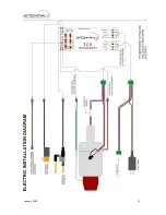
needs for its operation two different power supplies. The first is taken from the
radio receiver through the throttle servo connection and the second is the battery that
supplies the pump
. Reversing the polarity of the battery causes the destruction of the
semiconductors of the I.C.S.
The I.C.S. can work with pump battery voltages between 1.2V and 15V in manual start mode,
and from 4.8V to 15V in auto start mode. The selection of the number of battery elements is
define considering the real needs of the ancillary equipment like starter motor, solenoids
valves and pump motor.
Use only the supplied battery or a same voltage substitute.
This battery does not need an on/off switch in the airframe since the
I.C.S.
has an internal
electronic switch, which disconnects it when the power to the receiver is switched off.
3.3 Radio Receiver
The
I.C.S.
is connected to the radio receiver like a standard throttle servo, inserted in the
channel for the throttle, receiving the information of the throttle control pulses and the receiver
battery supply. The ECU can work with voltages from 4.8V to 9.9V from the receiver.
3.4 Thermocouple
The
I.C.S
. uses a thermocouple of type “K”, good up to 1100ºC. The provided standard
thermocouple consists of an Ø1.5 mm diameter Inconel wire, finished with a connector that
fits directly on the
I.C.S.
The recommended installation is by inserting the end of the
thermocouple so that it is 2 mm, 1/16 inch, within the flow of exhausts gases; and plugging
the lead into the
I.C.S.
at proper input. Take note that the wire coming from the thermo
coupler has a solid green wire and a green and white wire. The input of the
I.C.S.
is color-
coded; make sure to line up the correct colors when plugging in this lead.
Never bend or cut the probe or probe wires. If you need to extend the wire, use a servo
extension.
Summary of Contents for Rabbit
Page 1: ...OPERATION AND MAINTENANCE MANUAL...
Page 14: ...January 2009 13...
Page 15: ...January 2009 14...
Page 16: ...January 2009 15...
Page 17: ...January 2009 16...


