January, 2009
10
3 Turbine System Installation Instructions
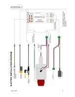
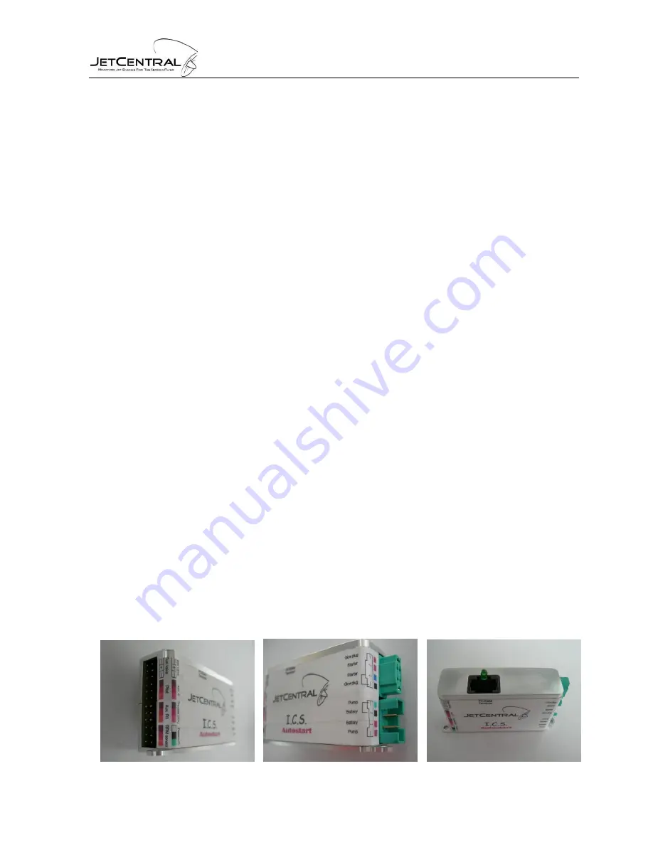
3.1 I.C.S.
Connections:
Throttle input to the receiver: JR type servo cable (Throttle RX)
Kerosen valve: JR type connector receptacle (Gas Valve)
Fuel valve: JR type connector receptacle. The central cable is positive and the two of
the sides negative (Fuel Valve)
RPM sensor: JR type connector receptacle (RPM Sensor)
Thermocouple: JR type connector receptacle (ThermoC)
Multiplex connector 1
Battery input: Red/black cable
Fuel pump: Red/Green cable
Multiplex connector 2
Glow plug: Red/Black cable
Starter: Red/Blue cable
Note: In all power cables the black is the common and negative. This means that all the black
cables are connected internally together and to the negative of the pump/starter battery.
Connect the cables in their places. Note that some of the JR type connectors used can be
connected in wrong place or inverted. Use the colored labels on the
I.C.S.
body to connect all
the connectors in their place. The configurations of the pins have manufacture to avoid
damage produced to the electronics in the case of a bad connection.
Please note that:
If the thermocouple connector is connected inverted, the temperature will decrease
when heated, and the
I.C.S.
will fail to recognize the gas ignition.
If the RPM sensor is connected inverted, no RPM will be read.
Use the recommended (supplied) starter motor battery or one of the same voltage. If
you decide to use a battery with different voltage, the turbine ECU has to be
readjusted at the factory.
Summary of Contents for Rabbit
Page 1: ...OPERATION AND MAINTENANCE MANUAL...
Page 14: ...January 2009 13...
Page 15: ...January 2009 14...
Page 16: ...January 2009 15...
Page 17: ...January 2009 16...


