background image

VM8013

2

4.

Place the radio in front of the dashboard opening so the wiring can be 
brought through the mounting sleeve. Follow the wiring diagram 
carefully and make certain all connections are secure and insulated 
with wire nuts or electrical tape. See “Wiring” on page 3. After 
completing the wiring connections, turn the unit on to confirm operation 
(vehicle ignition must be on). If the unit does not operate, re-check all 
wiring until the problem is corrected. 
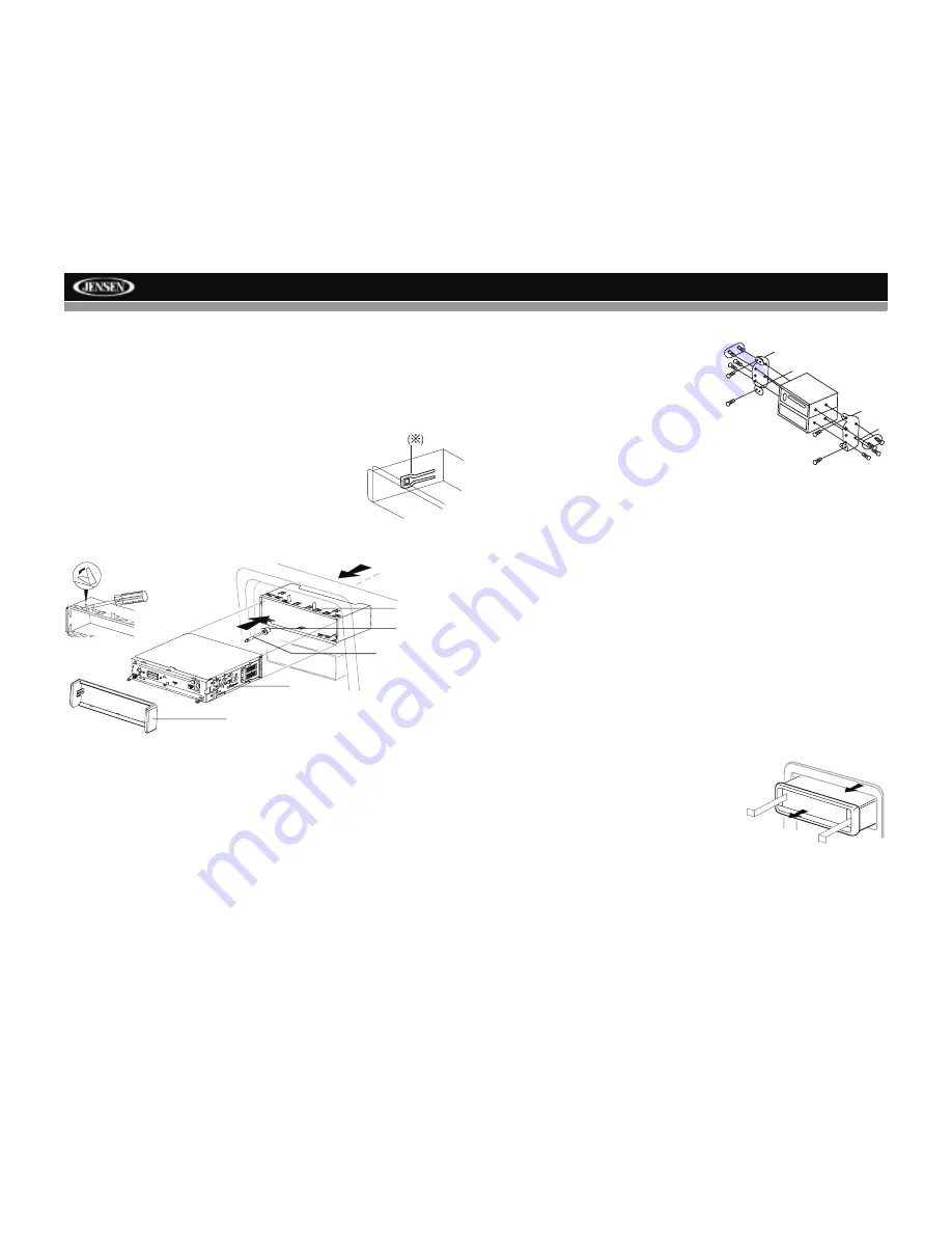
5.

Make sure the radio is right-side up, then 
carefully slide the radio into the mounting 
sleeve until it is fully seated and the spring clips 
lock it into place. 

6.

Secure the rear of the unit to the car body 
using the mounting bolt and rubber cushion.

7.

Test the radio using the “Operation” 
instructions that follow.

Kit Installation

If your vehicle requires the use of an installation kit to mount this radio, 
follow the instructions included with the installation kit to attach the radio to 
the mounting plate supplied with the kit.

1.

Wire and test the radio as outlined in the Mounting Sleeve Installation 
instructions.

2.

Install the radio/mounting plate assembly to the sub-dashboard 
according to the instructions in the installation kit.

3.

Replace the dashboard trim panel.

ISO Installation

This unit has threaded holes in the chassis 
side panels which may be used with the 
original factory mounting brackets of some 
vehicles to mount the radio to the 
dashboard. Please consult with your local 
car stereo shop for assistance on this type 
of installation.

1.

Remove the existing factory radio 
from the dashboard or center console 
mounting. Save all hardware and 
brackets as they will be used to mount the new radio.

2.

Carefully unsnap the plastic frame from the front of the new radio 
chassis. Remove and discard the frame.

3.

Remove the factory mounting brackets and hardware from the existing 
radio and attach them to the new radio. Do not exceed M5 x 9mm 
maximum screw size. Longer screws may damage components inside 
the chassis.

4.

Wire the new radio as outlined in the Mounting Sleeve Installation 
instructions.

5.

Mount the new radio assembly to the dashboard or center console 
using the reverse procedure of step 1.

Fuses

When replacing a fuse, make sure the new fuse is the correct type and 
amperage. Using an incorrect fuse could damage the radio.

Reconnect Battery

When wiring is complete, reconnect the battery negative terminal.

Removing the Radio

To remove the radio after installation, first 
remove the face plate. Next, remove the trim 
ring by firmly grasping one side and pulling. 
Insert the removal keys straight back until 
they lock, then pull the radio out. If the 
removal keys are inserted at an angle, they 
will not lock properly and will not release the 
unit.

Technical Assistance

If you require assistance, contact Technical Support at 1-800-323-4815 
from 9:00am to 6:00pm EST Monday through Friday.

SPRING CLIP   

MOUNTING

RUBBER

MOUNTING BOLT  

RADIO

TRIM RING   

BEND TABS   

SLEEVE

CUSHION

Summary of Contents for VM8013

Page 1: ...160 Watts Peak Watts en Cr te Vatios el M ximo 40W x 4 VM8013 Installation and Operation Manual SRC DIM PTY 1 2 3 4 5 6 BAND A V IN DN UP RPT RDM INT CH CAT DISP iPod Menu...

Page 2: ......

Page 3: ...tallation 1 Wiring 3 Front Panel Release 4 Remote Control 5 Operation 7 Satellite Radio Operation 10 Radio Operation 12 DISC MP3 WMA Playback 14 Controlling Your iPod 18 Setup Menu 19 Care and Mainten...

Page 4: ...ii VM8013...

Page 5: ...ys disconnect the battery negative terminal NOTE If the VM8013 is to be installed in a car equipped with an on board drive or navigation computer do not disconnect the battery cable If the cable is di...

Page 6: ...me vehicles to mount the radio to the dashboard Please consult with your local car stereo shop for assistance on this type of installation 1 Remove the existing factory radio from the dashboard or cen...

Page 7: ...ellow Black Subwoofer Out Parking Active Low Level Input Pink Camera In SAT R Red Video Out 1 SAT L White Video Out 2 Fuse 15A Camera Active High Level Input Green White SWC Steering Wheel Control Cha...

Page 8: ...m the chassis 4 Store the front panel it in the supplied carrying case to protect it from dirt and damage and take it with you to prevent theft Re attaching the Front Panel Before re attaching the fro...

Page 9: ...r the bottom of the front panel left of the LCD screen The remote control can operate within a distance of 3 5m Replacing the Battery When the range of operation of the remote control becomes short or...

Page 10: ...up down Volume up down Volume up down 11 MUTE Silence Audio Output Silence Audio Output Silence Audio Output Silence Audio Output Silence Audio Output 12 SEEK Search Next Previous Chan nel Press and...

Page 11: ...e turn the rotary encoder counter clockwise When volume is adjusted the volume level will be shown on the display panel as a number ranging from 0 lowest to 40 highest SWC Interface Optional The VM801...

Page 12: ...ary encoder to change to the 24 hour clock format Mirror Image This option allows for selection of a mirror image view when a rear view backup camera sold separately is connected to the CAMERA IN inpu...

Page 13: ...etting the unit will erase the time and preset memories It should only be activated upon initial installation after all wiring is complete or if there is a malfunction of any of the switches on the un...

Page 14: ...annel name is usually displayed Select a Band Press the BAND button 3 to change between three SAT bands SAT1 SAT2 and SAT3 Each band stores up to six preset stations Selecting a Station Press the or t...

Page 15: ...ect Channel Input To enter a radio station directly press the DISP button on the front panel 7 or remote control 23 three times to display the DIRECT channel input screen Enter the desired radio stati...

Page 16: ...the control panel Program type categories are listed allowing listeners to find similar programming by genre Press the TUNE TRACK or buttons 17 to select a category After a few seconds the radio will...

Page 17: ...e feature After entering the stations into memory the unit will automatically stop at each station for five seconds allowing you to preview each selection When using the Auto Store feature the new sta...

Page 18: ...3 WMA Play MP3 and WMA Windows Media Audio music files are digital audio files that are compressed to allow more files to be stored This unit can play MP3 WMA and video directly from files contained o...

Page 19: ...0 For character codes refer to the table to the right Entering File and Folder Names Names using the code list characters are the only file names and folder names that can be entered and displayed Us...

Page 20: ...nd hold the TUNE TRACK or buttons 17 or the buttons on the remote control to fast forward or fast reverse Press and hold once for 2X Press and hold additional times for 4X 8X 20X or PLAY Press the pla...

Page 21: ...Video Playback Features NOTE You cannot view video while driving the car When attempting to view video while the parking break is not engaged the following message will appear on the screen WARNING En...

Page 22: ...e control 6 to select the highlighted menu option Press the BAND button on the front panel 3 or remote control 25 to return to the previous menu Fast Forward Fast Reverse Press and hold the or buttons...

Page 23: ...enu LANGUAGE VIDEO AUDIO RATING MISC Video Format NTSC The color signals are output in the standard NTSC for mat PAL The color signals are output in the standard PAL format AUTO The color signal outpu...

Page 24: ...be closed Please refer to your software s recommended procedures for closing a disc session Review your recording software to familiarize yourself with the correct recording burning procedures We rec...

Page 25: ...rect connection to parking brake wire Check Parking SW wiring and correct Parking SW is connected but park ing brake is not engaged Stop vehicle in safe place and apply parking brake Flashing image or...

Page 26: ...y 30dB 9dBf Quieting Sensitivity 50dB 15dBf Alternate Channel Selectivity 70dB Signal to Noise Ratio 1 kHz 58dB Image Rejection 80dB Stereo Separation 1 kHz 30dB Frequency Response 30Hz 15 kHz 3dB AM...

Page 27: ...tenance section of your Installation and Operation Manual for additional information regarding the proper use of your product Limitations THE EXTENT OF THE COMPANY S LIABILITY UNDER THIS WARRANTY IS L...

Page 28: ...Audiovox Electronics Corporation Hauppauge NY 11788 Technical Assistance 1 800 323 4815 www jensen com 2008 Audiovox Ver 033108 Printed in China...

Reviews: