9
3.3 Installation instructions
Step1: Choose a proper site
Location requirement
If not specifically stated, our lifts are only for indoor use. It should be fixed on a smooth and solid concrete ground. Do not install
this lift on expansion beams of concrete or on a second or an elevated floor without first consulting building architect.
Make sure
that the space around or over the lift should be free of obstructions like heaters, building supports, electrical lines etc.
Step 2: Fix the installation layout
Once the installation site is determined, mark first the standing point of the four posts by a tape measure and chalk. Ensure two
diagonal lines are of the same length.
Step 3: Remove the packing materials
1. Place some wooden battens on the ground and then use a crane to have the packing rack removed on to the battens so as to
make its base is of some clearance from the ground.
2. Have the platforms of the lift suspended by a crane and then screw off the upside bolt and remove the first platform on to the
wooden battens initially prepared.
3. Screw off the downside bolt and take away the packing rack on both sides.
4. Remove the shock absorption plastic film with a knife.
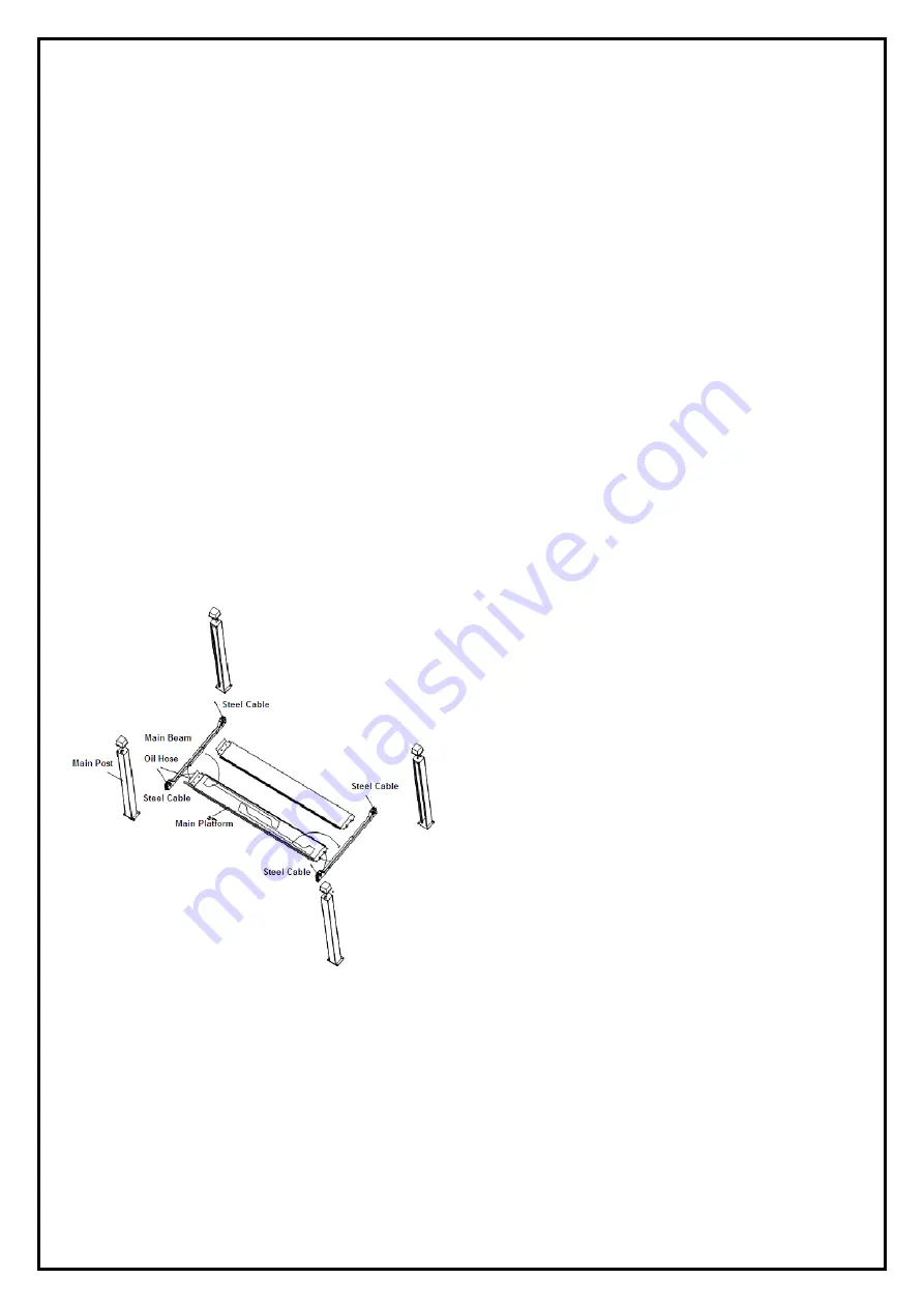
Step 4: Use a crane to have the general parts positioned in accordance with following layout.
For convenient installation, it would be better to pad something supporting under the platform.
Oil cylinder, steel cable and oil hose have already been fixed in the main platform before packing.
Wires rope, oil hose, safety lock etc, have already been fixed in the beams before packing.
Step5: Connect the platforms and beams
Firstly, connect the main beam with two platforms. Align accurately the screw sockets on the platform and the beam. Installers can
adjust the distance between two platforms on basis of practical needs. Once the distance was adjusted, fasten the beam and
platforms with M12*30 hex bolt with spring and flat washer padded. Connect the other beam in the same way.
Summary of Contents for JA5500F
Page 19: ...19 Annex2 Overall diagram...
Page 20: ...20 Annex3 Floor plan Annex 4 Steel cable connection...
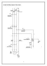
Page 22: ...22 Annex 6 Wiring diagram Three phase...
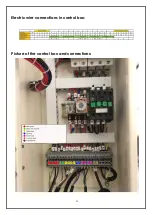
Page 23: ...23 Electric wire connections in control box Picture of the control box and connections...
Page 24: ...24...
Page 25: ...25...
Page 26: ...26...
Page 27: ...27 Annex7 Separate diagrams for the lift JA5500F...
Page 35: ...35 Annex9 Size and weight requirements on vehicles...
Page 36: ...36...


