background image

acceptable level, the tire can be rotated on the wheel.
(See Method 2).

METHOD 1 (RELOCATE WHEEL ON HUB)

(1) Drive vehicle a short distance to eliminate tire

flat spotting from a parked position.

(2) Check wheel bearings and adjust if adjustable

or replace if necessary.

(3) Check the wheel mounting surface.
(4) Relocate wheel on the mounting, two studs

over from the original position.

(5) Tighten wheel nuts until all are properly

torqued, to eliminate brake distortion.

(6) Check radial runout. If still excessive, mark

tire sidewall, wheel, and stud at point of maximum
runout and proceed to Method 2.

METHOD 2 (RELOCATE TIRE ON WHEEL)

NOTE: Rotating the tire on wheel is particularly
effective when there is runout in both tire and
wheel.

(1) Remove tire from wheel and mount wheel on

service dynamic balance machine.

(2) Check wheel radial runout (Fig. 3) and lateral

runout (Fig. 4).

STEEL WHEELS: Radial runout 0.040 in., Lat-

eral runout 0.045 in.

ALUMINUM WHEELS: Radial runout 0.030 in.,

Lateral runout 0.035 in.

(3) If point of greatest wheel lateral runout is near

original chalk mark, remount tire 180 degrees.
Recheck runout, Refer to match mounting procedure.

SERVICE PROCEDURES

WHEEL INSTALLATION

The wheel studs and nuts are designed for specific

applications. They must be replaced with equivalent
parts. Do not use replacement parts of lesser quality
or a substitute design. All aluminum and some steel
wheels have wheel stud nuts which feature an
enlarged nose. This enlarged nose is necessary to
ensure proper retention of the aluminum wheels.

Before installing the wheel, be sure to remove any

build up of corrosion on the wheel mounting surfaces.
Ensure wheels are installed with good metal-to-metal
contact.

To install the wheel, first position it properly on

the mounting surface. All wheel nuts should then be
tightened just snug. Gradually tighten them in
sequence to the proper torque specification (Fig. 5).

Fig. 2 Checking Tire/Wheel/Hub Runout

Fig. 3 Radial Runout

Fig. 4 Lateral Runout

22 - 8

TIRES AND WHEELS

TJ

DIAGNOSIS AND TESTING (Continued)

Summary of Contents for Wrangler 1997

Page 1: ...GROUP TAB LOCATOR Service Manual Comment Forms Rear of Manual...

Page 2: ......

Page 3: ...nufacturer and government agencies to verify the authenticity of the vehicle and official documenta tion The formula to use the check digit is not released to the general public POSITION INTERPRETATIO...

Page 4: ...ng BODY CODE PLATE LINE 3 DIGITS 1 THROUGH 12 LOCATION AND DECODING Vehicle Order Number A metal body code plate is attached to the floor pan under the drivers seat Fig 2 Disengage the snaps DIGITS 13...

Page 5: ...Canada M Mexico U United States DIGIT 6 Open Space VEHICLE EXTERIOR DIMENSIONS VEHICLE INTERIOR DIMENSIONS INTRODUCTION 3 DGG 32RH 3 speed Automatic DIGITS 7 THROUGH 23 Vehicle Identification Number...

Page 6: ...on SAE and Metric PR606B marks plus 2 The most commonly used metric bolt strength classes are 9 8 and 12 9 The metric strength class identification number is imprinted on the head of the bolt The high...

Page 7: ...que Values U S Customary SAE Grade Number 5 8 Bolt Head Markings kaffii These are all SAE Grade 5 3 line i Y Bolt Torque Grade 5 Bolt Bolt Torque Grade 8 Bolt Body Size Cast Iron Aluminum Cast Iron Al...

Page 8: ...6T head head No 7 7T No mark 8 8T 9 9T 4T 10 10T 11 11T 01 O No mark 4T Hexagon flange bolt O No mark 4T Grooved w washer hexagon bolt p 6T Hexagon u head bolt Two 5T O protruding U lines Wr Hexagon f...

Page 9: ...on meters N m Also use the chart to convert between millimeters mm and inches in TORQUE REFERENCES Individual Torque Charts appear at the end of many Groups Refer to the Standard Torque Specifi cation...

Page 10: ...79 66 48 6791 86 63 4303 7 9 4907 27 36 6071 47 63 7234 67 90 8398 87 117 9562 7 5 1629 27 19 9142 47 34 6654 67 49 4167 87 64 1679 8 10 8465 28 37 9629 48 65 0793 168 92 1956 88 119 3120 8 5 9005 28...

Page 11: ...6 16 1 5 11 40 1 400 101 6 1 8 80 69 in I6F 9 90 78 in I6f 8 1 25 19 195 14 21 210 15 6T 10 1 25 39 400 29 44 440 32 12 1 25 71 730 53 80 810 59 14 1 5 1 10 1 100 80 125 1 250 90 16 1 5 170 1 750 127...

Page 12: ......

Page 13: ...for general trans portation Schedule B lists maintenance intervals for vehi cles that are operated under the conditions listed at the beginning of the Maintenance Schedule section Use the schedule tha...

Page 14: ...grease is rated for quality and usage by the NLGI All approved products have the NLGI symbol Fig 3 on the label At the bottom NLGI symbol is the usage and quality identification letters Wheel bearing...

Page 15: ...t battery and clean and tighten terminals as required Check electrolyte level and add water as needed Check fluid levels of coolant reservoir power steering brake master cylinder and transmission and...

Page 16: ...drive belts Adjust as needed Lubricate steering linkage Drain and refill automatic transmission fluid Drain and refill transfer case fluid Inspect brake linings 97 500 Miles 156 000 km or at 78 month...

Page 17: ...ont and rear axles Inspect brake linings 51 000 Miles 82 000 km Change engine oil Replace engine oil filter Flush and replace engine coolant 54 000 miles 86 400 km Change engine oil Replace engine oil...

Page 18: ...km Change engine oil 69 000 Miles 110 000 km Replace engine oil filter Change engine oil Lubricate steering linkage Replace engine oil filter Drain and refill automatic transmission fluid Drain and re...

Page 19: ...r element sine bus snow plowing or other types of commercial Replace ignition cables service or prolonged operation with heavy loading Replace spark plugs especially in hot weather require front and r...

Page 20: ...mage o booster vehicle charging system can result INDEX BATTERY NEGATIVE CABLE Fig 1 Jumper Cable Clamp Connections TJ 2 When using another vehicle as a booster source turn off all accessories place g...

Page 21: ...he safety of the operator pedestrians or other motorists Do not attach tow chains T hooks J hooks or a tow sling to a bumper steering linkage drive shafts or a non reinforced frame hole GROUND CLEARAN...

Page 22: ...TOW STRAPSICHAI S COULD BREAK AND CAUSE SERIOUS INJURY TJ Some Jeep vehicles are equipped with front emer gency tow hooks The tow hooks should be used for EMERGENCY purposes only CAUTION DO NOT use e...

Page 23: ...used verify that the lifting pads are positioned properly WARNING THE HOISTING AND JACK LIFTING POINTS PROVIDED ARE FOR A COMPLETE VEHI LUBRICATION AND MAINTENANCE 0 11 CLE WHEN A CHASSIS OR DRIVETRAI...

Page 24: ......

Page 25: ...turns CAMBER is the inward or outward tilt of the wheel relative to the center of the vehicle Tilting the SUSPENSION CONTENTS ALIGNMENT INDEX page SUSPENSION 2 1 page page ADJUSTMENTS 4 PRE ALIGNMENT...

Page 26: ...CENTERLINE VERTICAL ii _ NEGATIVE CAMBER ANGLE PIVOT CENTERLINE SCRUB RADIUS POSITIVE CAMBER NOT SHOWN TOP OF WHEEL OUTBOARD THRUST ANGLE I ANGLE OF REAR AXLE RELATIVE TO VEHICLE CENTERLINE AXLE POIN...

Page 27: ...nents necessary EXCESSIVE PLAY IN STEERING 1 Loose or worn wheel bearings 1 Adjust or replace wheel bearings 2 Loose or worn steering or 2 Tighten or replace components as suspension components necess...

Page 28: ...ams on the lower suspension arm Fig 1 Changing caster angle will also change the front propeller shaft angle The propeller shaft angle has priority over caster Refer to Group 3 Differential and Drivel...

Page 29: ...Make sure the toe setting does SPECIFICATIONS not change during clamp tightening 5 Verify the right toe setting ALIGNMENT SPECIFICATIONS ADJUSTMENT PREFERRED RANGE CASTER 7 1 0 CAMBER fixed angle 0 25...

Page 30: ...mpers in compres sion and shocks absorbers in reb und Stabilizer Bar The stabilizer bar is used to con trol vehicle body roll during tur s The spring steel FRONT SUSPENSION page INDEX DIAGNOSIS AND T...

Page 31: ...he stabilizer bar links and shock absorbers from the axle 6 Disconnect the track bar from the frame rail bracket 7 Disconnect the drag link from the pitman arm 8 Lower the axle until the spring is fre...

Page 32: ...rm nut and bolt at the axle bracket Fig 3 3 Remove the nut and bolt at the frame rail and remove the upper suspension arm INSTALLATION 1 Position the upper suspension arm at the axle and frame rail 2...

Page 33: ...to 95 N m 70 ft lbs 3 Install upper link nuts and tighten to 61 N m 45 ft lbs 4 Install bumper valence TRACK BAR CAUTION Use a universal puller tool to separate the track bar ball stud from the frame...

Page 34: ...INSTALLATION 1 Install the hub bearing and brake dust shield to the knuckle 2 Install the hub to knuckle bolts and tighten to 102 N m 75 ft lbs 3 Install the hub washer and nut Tighten the hub nut to...

Page 35: ...n lbs Suspension Arm Lower Axle Bracket Nut 115 N m 85 ft lbs Frame Bracket Nut 176 N m 130 ft lbs Suspension Arm Upper Axle Bracket Nut 75 N m 55 ft lbs Frame Bracket Bolt 75 N m 55 ft lbs Stabilizer...

Page 36: ...the bar to frame brackets The bar is isolated by rubber bushings Track Bar The track bar is sed to control rear axle lateral movement The track bar is attached to a frame rail bracket and an axle brac...

Page 37: ...move the supports and lower the vehicle 5 Tighten the stabilizer bar links shock absorb ers and track bar to specified torque LOWER SUSPENSION ARM REMOVAL 1 Raise and support the vehicle 2 Remove the...

Page 38: ...STABILIZER BAR REMOVAL 1 Raise and support the vehicle 2 Remove the stabilizer bar link bolts from the frame mounts Fig 5 3 Remove the link bolts from the stabilizer bar 4 Remove the stabilizer bar re...

Page 39: ...e necessary to pry the axle assem bly over to install the track bar 3 Remove supports and lower the vehicle 4 Tighten the track bar nut bolt at both ends to 100 N m 74 ft lbs SPECIFICATIONS TORQUE CHA...

Page 40: ......

Page 41: ...H 8 SERVICE PROCEDURES BRAKE BLEEDING I 12 BRAKE DRUM MACHINING 13 BRAKE FLUID LEVEL 12 BRAKE LINE 13 DISC ROTOR MACHINING II 12 MASTER CYLINDER 12 BRAKES INDEX BRAKES 5 1 page page REMOVAL AND INSTAL...

Page 42: ...on fluid or any fluid containing mineral oil to clean the system components These fluids damage rubber cups and seals Use only fresh brake fluid or Mopar brake cleaner to clean or TJ flush brake syste...

Page 43: ...ric pressure d for booster oper ngine intake mani pheric pressure is at the rear of the f the booster dia from the intake he rear of the dia Fig 1 Power Brake Booster Typical phragms are exposed to no...

Page 44: ...equal Fig 3 Fluid pressure applied to the piston is transmitted directly to the inboard brake shoe This forces the shoe lining against the inner surface of the disc brake rotor At the same time fluid...

Page 45: ...application device The front cable is connected between the hand lever and the ten sioner The tensioner rod is attached to the equalizer TRAILING DIUSTER SHOE EVER PRING PARK BRAKE STRUT ADJUSTER AND...

Page 46: ...er b If fluid appears contaminated drain out a sample System will have to be flushed if fluid is separated into layers or contains a substance other than brake fluid The system seals and cups TJ will...

Page 47: ...ion for causes BRAKE PULL Possible causes for front brake pull condition are Contaminated lining in one caliper Seized caliper piston Binding caliper Loose caliper Rusty adapter caliper slide surfaces...

Page 48: ...ply separation can cause pull and vibration STOP LAMP SWITCH Stop lamp switch operation can be tested with an ohmmeter The ohmmeter is used to check continuity between the pin terminals at different...

Page 49: ...or one minute 3 Observe the vacuum supply If vacuum supply is not adequate repair vacuum supply 4 Clamp hose shut between vacuum source and check valve 5 Stop engine and observe v cuum gauge 6 If vacu...

Page 50: ...ontact surface Replace the rotor if worn below minimum thickness or if machining would reduce thickness below the allowable minimum Rotor minimum thickness is usually specified on the rotor hub The sp...

Page 51: ...um surface machined oversize Front cable not secured to lever Rear cable not attached to lever Rear cable seized BRAKES 5 11 Brake shoes reversed Parking brake strut not seated in shoes Parking brake...

Page 52: ...istributed throughout the TJ BLEEDING RH232 TUBES HOUSING DOWEL MASTER CYLINDER Fig 13 Master Cylinder Bleeding hydraulic system This will make additional bleeding operations necessary Do not allow th...

Page 53: ...surface variation Final finish cuts of 0 025 to 0 038 mm 0 001 to 0 0015 in are recommended and will gen erally provide the best surface finish Be sure the drum is securely m Ounted in the lathe befor...

Page 54: ...d Flare Tools RH222 REMOVAL AND INSTALLATION STOP LAMP SWITCH REMOVAL 1 Remove steering column cover and lower trim panel for switch access if necessary 2 Press brake pedal downward to fully applied p...

Page 55: ...n to 37 N m 27 ft lbs 6 Install stud plate or clutch cylinder if equipped and tighten mounting nut to 28 11V m 21 ft lbs Install retainer clip securing booster push rod to pedal Fig 18 and clutch rod...

Page 56: ...studs and tighten mounting nuts to 24 N m 18 ft lbs 5 Install brake lines to master cylinder and com bination valve by hand to avoid cross threading 6 Tighten master cylinder brake lines to 15 N m 11...

Page 57: ...hank ength greater than 67 6 mm 2 66 in they may contact the inboard brake shoe causing a partial apply condition Refer to Figure 14 for the required calliper bolt length 5 Position front brake hose c...

Page 58: ...iper weight 9 Wipe caliper off with shop rags or towels Do not use compressed air Fig 28 Inboard Brake Shoe Removal INSTALLATION 1 Clean brake shoe mounting ledge slide surfaces of steering knuckle wi...

Page 59: ...assemble 2 Remove caliper 3 Remove retainers securing rotor to hub studs Fig 32 4 Remove rotor from hub 5 If rotor shield requires service remove front hub and bearing assembly DRUM BRAKE SHOES ROTOR...

Page 60: ...Typical SUPPORT PLATE J9005 14 WHEEL CYLINDER CYLINDER TO SUPPORT SEAL J9005 13 TJ 5 Attach parking brake lever to secondary brake shoe Use new washer and U clip to secure lever 6 Remove wheel cylinde...

Page 61: ...ver and remove lever assembly from vehicle Fig 35 Parking Brake Cable Attachment L R CABLE R R CABLE 80alc38a INSTALLATION 1 Install front cable on lever assembly 2 Install lever assembly on mounting...

Page 62: ...REMOVAL 1 Remove reservoir cap and empty fluid into drain container 2 Remove pins that retain reservoir to master cylin der Use hammer and pin punch to remove pins Fig 40 III1111111111 PIN PUNCH ROLL...

Page 63: ...before installation in vehicle 3 Pad interior of caliper with minimum 2 54 cm 1 in thickness of shop towels or rags Fig 45 Towels are needed to protect caliper piston during removal Fig 45 Padding Cal...

Page 64: ...ore new piston seal and piston with clean brake fluid 2 Lubricate caliper bushings and interior of bushing boots with Dielectric silicone grease I TJ 3 Install bushing boots in caliper then insert bus...

Page 65: ...cup is facing inward toward spring and expander and flat side is against piston 3 Install spring and expander followed by remaining piston cup and piston 4 Install boots on each end of cylinder and i...

Page 66: ...he springs Inspect the brake shoe contact pads on the support plate replace the support plate if any of the pads are worn or rusted through Also replace the plate if it is bent or distorted Fig 57 WHE...

Page 67: ...ehicle NOTE Do not loosen tighten equalizer adjusting nut for any reason after completing adjustment Fig 58 Tensioner Rod Measurement J9405 158 REAR DRUM BRAKE The rear drum brakes are equipped with a...

Page 68: ...plugs 11 Adjust parking brake cable and lower vehicle 12 Install brake drums and wheels and lower vehicle 13 Drive vehicle and make one forward stop fol lowed by one reverse stop Repeat procedure 8 1...

Page 69: ...lbs Brake Lines 1 15 N m 11 ft lbs Combination Valve Mounting Nuts II 24 N m 18 ft lbs Brake Lines 1 21 N m 15 ft lbs Caliper Installer Caliper Dust Boot C 4842 Mounting Bolts 15 N m 11 ft lbs Brake...

Page 70: ...Acceleration Switch Main Relay And Pump Motor Relay ABS Warning Light Pump Motor Sensor DIESCRIPTION AND OPERATION ANTILOCK BRAKE SYSTEM Battery voltage is supplied to the CAB ignition ter minal when...

Page 71: ...can be measured in milliseconds CONTROLLER ANTILOCK BRAKES The CAB is located under the instrument panel to the right side of the steering column It is mounted to bracket with one bolt The bracket is...

Page 72: ...kles The rear sensors are mounted to the rear brake backing plate j The sensors convert wheel speed into a small AC electrical signal This signal is transmitted to the CAB The CAB convert the AC signa...

Page 73: ...r the pump motor only The pump motor relay starts stops the pump motor when signaled by the CAB The relays are located in the power distribution box in the engine compartment ABS WARNING LAMP The ambe...

Page 74: ...d install the mounting REMOVAL 1 Disconnect and isolate the negative battery ter minal 2 Disconnect the HCU harness connectors 3 Remove all the brake lines from the HCU Fig 7 4 Remove HCU mounting bol...

Page 75: ...move clips securing sensor wires to brake lines rear axle and brake hose 5 Unseat sensor wire support plate grommet 6 Remove bolt attaching sensor to bracket and remove sensor BRAKES 5 35 INSTALLATION...

Page 76: ...ER MASTER CYLINDER HCU 80al8d4c COMBINATION VALVE BRACKET Fig 13 Combination Valve Bracket 80al8d4f INSTALLATION 1 Position valve bracket on booster studs and tighten bracket attaching nuts to 17 N m...

Page 77: ...k into position ARROW INDICATES FRONT OF SWITCH FOR PROPER MOUNTING J9505 94 Fig 15 Acceleration Switch Position Indicator SPECIFICATIONS TORQUE CHART BRAKES 5 37 DESCRIPTION TORQUE Acceleration Senso...

Page 78: ......

Page 79: ...is connected to the clutch pedal The slave cylinder push rod is connected to the clutch release fork The master cyl inder is mounted on the driver side of the dash panel CLUTCH CONTENTS CLUTCH 6 1 pag...

Page 80: ...mounted on the transmission front bearing retainer The bearing is attached to the release lever which moves the bear ing into contact with the clutch cover diaphragm spring Slave cylinder force cause...

Page 81: ...se bearing unless actually faulty Replace bearing only if seized noisy or damaged 11 Check clutch cover diaphragm spring and release fingers Replace cover if spring or fingers are bent warped broken c...

Page 82: ...eal Tighten flywheel bolts to specified torque only Overtightening can dis tort the flywheel hub causing runout TJ CLUTCH COVER AND DISC RUNOUT Check the clutch disc before installation Axial face run...

Page 83: ...rts order or model number 1 Rough handling impact bent cover spring or disc Incorrect bolt tightening sequence and method caused warped cover 1 Flywheel surface scored and nicked 1 Frequent operation...

Page 84: ...clutch fluid level 2 Clutch cover loose 3 Wrong clutch disc 4 Disc bent distorted during installation 5 Clutch cover diaphragm spring bent or warped during transmission installation 6 Clutch disc ins...

Page 85: ...related problem 1 Clutch pressure plate position setting incorrect or modified 2 Clutch cover spring or release fingers bent distorted rough handling improper assembly 3 Clutch disc damaged or distort...

Page 86: ...le operation 1 Clutch cover incorrect or release fingers are bent or distorted causing damage 2 Release bearing defect 3 Release bearing misaligned 1 Release bearing defect 1 Pivot pin loose Pedal bus...

Page 87: ...aulic system should not require additional fluid under normal circumstances The reservoir fluid level will actually increase as normal clutch wear occurs Avoid overfilling or remov ing fluid from the...

Page 88: ...nt gear will cause uneven heating and expansion The torch flame can also anneal the gear teeth resulting in rapid wear and damage after installation 5 The heated gear must be installed evenly to avoid...

Page 89: ...lt tighten 3 large bolts all the way any sequence 11 Apply light coat of Mopar high temperature bearing grease to pilot bearing hub and splines of transmission input shaft Do not over lubricate shaft...

Page 90: ...ing to transmission bolts is 38 N m 28 ft lbs NOTE Be sure the transmission and housing mat ing surfaces are clean before installing an original or replacement clutch housing Dirttforeign material tra...

Page 91: ...Raise vehicle 7 Insert slave cylinder push rod through clutch housing opening and into release lever Be sure cap on end of rod is securely engaged in lever Check this before installing cylinder attac...

Page 92: ...utch cover 4 0 L 52 N m 38 ft lbs Nut clutch master cyl 38 N m 28 ft lbs Nut clutch slave cyl 23 N m 17 ft lbs Bolt clutch housing M12 75 N m 55 ft lbs Bolt clutch housing 3 8 37 N m 27 ft lbs Bolt cl...

Page 93: ...normal operating temperature and prevents over heating COOLING SYSTEM 7 1 page VISCOUS FAN DRIVE 20 WATER PUMP 8 SERVICE PROCEDURES ADDING ADDITIONAL COOLANT 23 COOLANT SERVICE 22 DRAINING COOLING SY...

Page 94: ...around the coolant Coolant flows through the engine water jackets absorbing heat produced during engine operation The coolant carries heat to the radiator and heater core Here it is transferred to the...

Page 95: ...N AND OPERATION TRANSMISSION OIL COOLER WATER TO OIL COOLER All models equipped with an automatic transmis sion are equipped with a transmission oil cooler mounted internally within the radiator tank...

Page 96: ...P is stamped on the front flange next to the air bleed The words TO RAD are stamped on one arm of the thermostat They indicate the proper installed position The same thermostat is used for winter and...

Page 97: ...the vacuum valve to open and cool ant in reserve overflow tank to be drawn through connecting hose into radiator If the vacuum valve is stuck shut radiator hoses will collapse on cool down A rubber g...

Page 98: ...w driver or a hex socket To prevent damage to hoses or clamps the hose clamps should be tightened to 4 N m 34 in lbs torque Do not over tighten hose clamps TJ TYPICAL HOSE TYPICAL CONSTANT TENSION HOS...

Page 99: ...e to a viscous fan drive malfunction DIAGNOSIS AND TESTING ON BOARD DIAGNOSTICS OBD FOR CERTAIN COOLING SYSTEM COMPONENTS The powertrain control module PCM has been programmed to monitor the certain f...

Page 100: ...ostic Trouble Code DTC number 35 is indicated After any stored DTC information has been observed the display will end with a flashing DTC number 55 This will indicate the end of all stored information...

Page 101: ...However cracks running along a rib not across are not nor mal Any belt with cracks running along a rib must be replaced Fig 14 Also replace the belt if it has excessive wear frayed cords or severe gl...

Page 102: ...en component bearing failure 4 Belt glazed and hardened from heat and excessive slippage 1 Belt tension either too high or too low 2 Pulley s not within design tolerance 3 Foreign object s in grooves...

Page 103: ...nt induced vibration 6 System resonant frequency induced vibration 1 Tension sheeting contacting stationary object 2 Excessive heat causing woven fabric to age 3 Tension sheeting splice has fractured...

Page 104: ...NDITIONING ADD ON OR AFTER MARKET A maximum cooling package should have been ordered with vehicle if add on or after market A C is TJ installed If not maximum cooling system compo nents should be inst...

Page 105: ...oard Diagnostics in the service manual text Replace thermostat if necessary If a Diagnostic Trouble Code DTC number 17 has not been set the problem may be with the temperature gauge 2 Check the engine...

Page 106: ...of radiator filler neck If neck is bent or damaged replace radiator c Check the condition of the hose from the radiator to the coolant tank It should fit tight at both ends without any kinks or tears...

Page 107: ...water pump slipping 9 Air leak on the suction side of water pump allows air to build up in cooling system causing thermostat to open late CORRECTION 1 A normal condition No correction is necessary 2...

Page 108: ...rive has defective bearing 5 A certain amount of fan noise roaring may be evident on models equipped with a thermal viscous fan drive Some of this noise is normal 1 Check condition of radiator cap and...

Page 109: ...cated on one of the heater hoses This valve maybe defective 6 Water pump is not pumping water to heater core When the engine is fully warmed up both heater hoses should be hot to the touch If only one...

Page 110: ...tor steam may be emitted This usually occurs in cold weather with no fan or airflow to blow it away 1 Coolant color is not necessarily an indication of adequate corrosion or temperature protection Do...

Page 111: ...d check the coolant level Push down on the cap to disengage it from the stop tabs Wipe the inner part of the filler neck and examine the lower inside sealing seat for nicks cracks paint dirt and solde...

Page 112: ...clean container for reuse WARNING DO NOT REMOVE THE CYLINDER BLOCK DRAIN PLUGS OR LOOSEN THE RADIATOR DRAINCOCK WITH THE SYSTEM HOT AND UNDER PRESSURE SERIOUS BURNS FROM COOLANT CAN OCCUR TJ Drain suf...

Page 113: ...ION Engines equipped with serpentine drive belts have reverse rotating fans and viscous fan drives They are marked with the word REVERSE to designate their usage Installation of the wrong fan or visco...

Page 114: ...replacement INSPECTION Visually inspect the pressure valve gasket on the cap Replace cap if the gasket is swollen torn or worn Inspect the area around radiator filler neck for white deposits that ind...

Page 115: ...ant from the reserve overflow tank Open the radiator draincock and when the tank is empty remove the radiator cap The coolant does not have to be removed from the tank unless the system is being refil...

Page 116: ...VAL AND INSTALLATION AUTOMATIC TRANSMISSION OIL COOLER The internal transmission oil cooler located within the radiator is not serviceable If it requires service the radiator must be replaced Once the...

Page 117: ...of the pump shaft and bearing assembly The water pump is serviced only as a complete assembly WARNING DO NOT REMOVE THE BLOCK DRAIN PLUG S OR LOOSEN RADIATOR DRAINCOCK WJTH THE SYSTEM HOT AND UNDER PR...

Page 118: ...S ALWAYS WEAR SAFETY GLASSES WHEN SERVIC ING CONSTANT TENSION CLAMPS HOSE CLAMP HOSE TOOL 6094 CLAMP Fig 25 Hose Clamp Took Typical Fig 24 Power Steering Pump Attachment J9207 36 CAUTION A number or l...

Page 119: ...orque Rotate the shaft by hand to be sure it turns freely 4 Connect the radiator and heater hoses to the water pump 5 Position water pump pulley to water pump hub 6 Install fan and four nuts to water...

Page 120: ...housing unevenly or with the thermostat out of its recess may result in a cracked housing 5 Tighten the housing bolts to 20 N m 15 ft lbs torque TJ GROOVE J9307 25 Fig 29 Thermostat Recess 6 Install h...

Page 121: ...ank if equipped Install and tighten four mounting bolts to 8 N m 72 in lbs torque 4 If equipped remove plugs and connect auto matic transmission fluid cooler lines 5 Connect radiator hoses and install...

Page 122: ...ain engines may require the removal of the fan shroud to remove the viscous fan drive The fan shroud and fan blade viscous fan drive should be removed from the vehicle as one assembly 4 Remove four fa...

Page 123: ...but the belt BELT SCHEMATICS The belt routing schematics are published from the latest information available at the time of publica tion Vehicles not equipped with Power Steering have an idler pulley...

Page 124: ...installed until upper radia tor hose is hot Stop engine and drain water from Fig 36 Power Steering Pump Bracket and Idler Pulley PUMP ASSEMBLY PUMP ASSEMBLY 4 OL 2 5L TJ 8020cdae system If water is di...

Page 125: ...CITIES COOLING SYSTEM 7 33 from exhaust manifolds and pipe fan blades drive belts and sway bars Improperly positioned hoses can be damaged resulting in coolant loss and engine overheating Ordinary wor...

Page 126: ...ge TORQUE DESCRIPTION TORQUE Generator Pivot Bolt 38 N m 28 ft lbs Generator Rear Adjusting Bolt 27 N m 20 ft lbs Auto Trans Auxiliary Oil Cooker Mounting Bolts 2 N m 18 in lbs Fan Blade to Viscous Fa...

Page 127: ...done through universal joints which permit the propeller shaft to operate at different angles The slip joints or yokes permit contraction or expan ion Fig 1 Tubular propeller shafts are bal nced by th...

Page 128: ...ller Shafts NEEDLE BEARING YOKE REAR PROPELLER SHAFT SEAL Fig 2 Single Cardan Universal Joint TJ REAR AXLE 80a53ac2 SPIDER NEEDLE BEARING PRECAUTIONS Use exact replacement hardware for attaching the p...

Page 129: ...lanced will cause a low frequency vibration Refer to Group 22 Wheels and Tires for additional information Brake drums that are unbalanced will cause a harsh low frequency vibration Refer to Group 5 Br...

Page 130: ...the wheel lug nuts to retain the brake drums 3 Mark and number the shaft six inches from the yoke end at four positions 90 apart 4 Run and accelerate the vehicle until vibration occurs Note the intens...

Page 131: ...shafts consider each shaft separately On 4WD vehicles the front shaft input pinion shaft angle has priority over the caster angle Ideally the driveline system should have Angles that are in equal or o...

Page 132: ...urement j can also be taken at the rear end of the shaft This measurement will give you the Propeller Shaft Angle C 4 Subtract smaller figure from larger C minus A to obtain Transmission Output Operat...

Page 133: ...ansfer case and remove the propeller shaft Horizontal Level DIFFERENTIAL AND DRIVELINE 3 7 Trans Output Operating Angle 1 90 Axle Input Operating Angle 1 70 Amount of U J6int Cancellation 0 20 Fig 12...

Page 134: ...Crimp clamp to hold dust boot to propeller shaft yoke Fig 17 4 Lower the vehicle SPECIAL TOOL C 4975 A Fig 17 Crimping Dust Boot Clamp Typical DISASSEMBLY AND ASSEMBLY SINGLE CARDAN BOOT 80a5O357 REM...

Page 135: ...d align it with the cross hole Fig 2 Keep the needle bearings upright in the bearing assembly A needle roller lying at the bottom will prevent proper assembly DIFFERENTIAL AND DRIVELINE 3 9 BEARING Fi...

Page 136: ...t marks on the yokes and propeller shaft for installation refer ence 3 Remove all the bearing assembly snap rings Fig 23 Fig 23 Remove Snap Rings J9316 5 TJ 4 Press the bearing assembly partially from...

Page 137: ...e that the spiders and yokes are aligned to the preference marks 1 Fit a cross into the tube y ke Fig 27 I Fig 27 Install Cross In Yoke J9316 9 DIFFERENTIAL AND DRIVELINE 3 11 2 Place a bearing assemb...

Page 138: ...ring assemblies on the remaining cross opposite sides Fit the open trunnions into the center yoke holes and the bearing assemblies into the centering kit Fig 33 Fig 32 Install Centering Kit Fig 33 Ins...

Page 139: ...fr nt shaft input pin ion shaft angle has priority over the caster angle A cam service kit is available to adjust the rear propeller shaft angle The cam ki is installed in the upper suspension arms at...

Page 140: ...ELINE SPECIFICATIONS IAL TOOLS PROPELLER SHAFTS AND U JOINTS PROPELLER SHAFT DESCRIPTION TORQUE Front Shaft Transfer Case Yoke Bolts 2 N nu 20 ft lbo Axle Yoke Bolts 19 N m 14 ft lbe Rear Shaft Axle Y...

Page 141: ...assembly S brake sensors nuckle assemblies axle shaft Do not he sensor when ides a means far ential INDEX DIFFERENTIAL AND DRIVELINE 3 15 page HUB BEARING AND AXLE SHAFT 21 INNER AXLE SHAFT OIL SEAL...

Page 142: ...input torque applied to the gears is divided and distributed equally between the two side gears As a result the pinion gears revolve with the pinion mate shaft but do not rotate around it Fig 1 When t...

Page 143: ...have a c This noise changes only with v bearing noise will be higher bec faster rate Drive the vehicle an tial If bearing noise occurs the p nion rear bearing is heard pinion gear bearings r damaged B...

Page 144: ...t tube alignment 2 Replace broken axle shaft Avoid excessive weight on vehicle 3 Replace broken axle shaft after inspecting for other possible causes Avoid erratic use of clutch 4 Replace broken axle...

Page 145: ...n flush and refill with correct amount of the correct lubricant 3 Readjust bearings 4 Inspect gears for excessive wear or scoring Replace as necessary 5 Readjust ring gear backlash and inspect gears f...

Page 146: ...bilizer bar link at the axle bracket 7 Disconnect the shock absorbers from axle bracket 8 Disconnect the track bar from the axle bracket 9 Disconnect the tie rod and drag link from the steering knuckl...

Page 147: ...Hub Knuckle and Axle Shaft DIFFERENTIAL AND DRIVELINE 3 21 7 On disconnect axles remove vacuum shift motor housing Refer to Vacuum Disconnect Axle in this section 8 Remove the axle shaft from the hou...

Page 148: ...eering knuckle with a brass ham mer to loosen Remove knuckle from axle tube yokes Fig 5 UPPER BALL STUD REPLACEMENT 1 Position tools as shown to remove and install ball stud Fig 6 LOWER BALL STUD REPL...

Page 149: ...tallation reference 5 Remove propeller shaft from the yoke 6 Rotate the pinion gear by hand several times to verify bearing smoothness 7 Measure amount of torque pinion gear with an in lbs dial 1 Reco...

Page 150: ...on Install yoke on pinion gear with Installer W 162 D and Holder 6958 Fig 12 PINION SPECIAL TOOL YOKE L i W 162 D r L CAUTION Do not exceed the minimum tightening torque when installing the pinion yok...

Page 151: ...ft side of the differential housing Attach Dial Indicator C 3339 to housing pilot stud Load the indicator lever against the opposite side of the hosing Fig 17 and zero the indicator face to the poin e...

Page 152: ...Gear Backlash paragraph in the Adjustments section to determine proper shim selection 1 Position Spreader W 129 B with dowel pins inserted into access holes in axle housing Fig 20 SPECIAL TOOL C 3339...

Page 153: ...differential case with Puller Press C 293 PA C 2912 39 Blocks 3 from Puller Press Set C 293 M and A apter C 293 3 Fig 23 DIFFERENTIAL AND DRIVELINE 3 27 ADAPTERS Fig 23 Differential Bearing Removal D...

Page 154: ...on yoke nut and washer Fig 26 5 Using Remover C 452 and Holder 6958 remove the pinion yoke from pinion shaft Fig 27 6 Remove the pinion gear and collapsible spacer from housing Fig 28 Catch the pinion...

Page 155: ...p bore in axle housing Record the thickness of the depth shims and baffel J9302 23 Fig 30 Rear Bearing Cup Removal Removal J9302 22 HANDLE 12 Remove the collapsible preload spacer from pinion gear Fig...

Page 156: ...nner pinion bearing cup Install the bearing cup with Installer D 146 and Driver Handle C 4171 Fig 33 Verify cup is correctly seated INSTALLER HANDLE 19402 66 Fig 33 Pinion Inner Bearing Cup Installati...

Page 157: ...play is taken up Fig 39 10 Slowly tighten the nut in small increments until the rotating torque is achieved Measure the preload torque frequently to avoid over crushing the collapsible spacer Fig 40 3...

Page 158: ...to avoid distorting the yoke do not over tighten the vise jaws 1 Remove the bearing cap retaining snap rings Fig 42 Fig 42 Axle Shaft Outer U Joint J8902 15 It can be helpful to saturate the bearing c...

Page 159: ...NDARD DIFFERENTIAL J8902 16 Removal 11 of wheel bearing EP lithium base ke Insert the seals aps into the yoke er in position gainst one bearing socket wrench in a the bearing caps ough to install the...

Page 160: ...ken dented surfaces on the bearing rollers or the roller contact surfaces Bearing cups must not be distorted or cracked Machined surfaces should be smooth and with out any raised edges Raised metal on...

Page 161: ...n dard If the number is negative a d that value to the required thickness of the depth shims baffle If the number is positive subtract that value from the thickness of the depth shim baffle If the num...

Page 162: ...les Choose proper step for axle being serviced 5 Assemble Dial Indicator C 3339 into Scooter Block D 115 2 and secure set screw 6 Place Scooter Block Dial Indicator in position in axle housing so dial...

Page 163: ...nd gear back lash measurements measure the pinion gear depth and prepare the pinion gear ford installation Estab lishing proper pinion gear depth essential to estab lishing gear backlash and toot cont...

Page 164: ...ntial Dummy Side Bearing 8 Thread guide stud C 3288 into rear cover bolt hole below ring gear Fig 57 9 Attach a dial indicator C 3339 to guide stud Position the dial indicator plunger on a flat surfac...

Page 165: ...m from the dial indicator reading to compensate for backlash between ring and pinion gears This tot 1 is the thickness shim required to achieve proper acklash 27 Subtract the backlash s im thickness...

Page 166: ...has been adjusted correctly The backlash can be adjusted within specifications to achieve desired tooth contact patterns 1 Apply a thin coat of hydrated ferric oxide or equivalent to the drive and coa...

Page 167: ...THE COAST SIDE OF TOOTH BUT MAY BE SLIGHTLY TOWARD THE TOE THERE SHOULD ALWAYS BE SOME CLEARANCE BETWEEN CONTACT PATTERN AND TOP OF THE TOOTH RING GEAR BACKLASH CORRECT THINNER PINION GEAR DEPTH SHIM...

Page 168: ...Hole Plug 34 N m 25 ft lbs Diff Cover Bolt 41 N m 30 ft lbs Bearing Cap Bolt 61 N m 45 ft lbs Ring Gear Bolt 95 122 N m 70 90 ft lbs Axle Nut 237 N m 175 ft lbs Wheel Brg Bolt 102 N m 75 ft lbs Lower...

Page 169: ...TJ a DIFFERENTIAL AND DRIVELINE 3 43 SPECIAL TOOLS Continued Installer D 11 2 Installer D 144 Installer D 146 Remover D 147 Remover D 148 Remover D 149 Installer D163 Installer W 162 D...

Page 170: ...FERENTIAL AND DRIVELINE TJ SPECIAL TOOLS Continued Installer 6228 Installer W 262 Remover Installer 6289 Spreader W 129 B Remover Installer 6288 w 0 rlam Tool Set Pinion Depth 6774 Installer 6764 Hold...

Page 171: ...DIFFERENTIAL AND DRIVELINE 3 45 SPECIAL TOOLS Continued 1 V8 HEX TURNBUCKLE 1 1 4 HEXTURNBUCKLE Puller 7794 14 Remover 79116 Adapter Set 6987 Screw Forcing 7918 Installer 791 Support 7919 Remover 792...

Page 172: ...xpansion The 194 RBI is equipped with semi floating axle shafts Vehicle loads are supported by the axle shaft and bearings The axle shafts are retained by C clips in the differential side gears The di...

Page 173: ...e shaft and are free to rotate on the shaft The pinion gear is fitted in a bore in the differential case and is positioned at a right angle to the axle shafts In operation power flow occurs as follows...

Page 174: ...ncorrect lubricant Foreign matter water contamination Incorrect bearing preload torque adjustment Axle gear problem conditions are usually the result o Insufficient lubrication Incorrect or contaminat...

Page 175: ...en springs Damaged axle shaft bearings Loose pinion gear nut Excessive pinion yoke run out Bent axle shaft DIFFERENTIAL AND DRIVELINE 3 49 Check for loose or damaged front end components or engine tra...

Page 176: ...rear axle shaft is most likely the cause TJ LIMITED SLIP DIFFERENTIAL Under normal traction conditions engine torque is divided evenly With low traction surfaces engine torque is transferred to the wh...

Page 177: ...ed Fill rear differential housing to required capacity with proper lubricant Refer to Specifications LOSS OF LUBRICANT I 1 Lubricant level too high 1 Drain excess lubricant by removing fill plug and a...

Page 178: ...worn or scored yoke and seal 6 Remove cover and clean flange and reseal 1 Refill differential housing 2 Drain flush and refill with correct amount of the correct lubricant 3 Readjust bearings 4 Inspe...

Page 179: ...se one rear wheel until it is completely off the ground 4 Remove wheel and bolt Special Tool 6790 to studs 5 Use torque wrench on special tool to rotate wheel and read rotating torque Fig 5 6 If rotat...

Page 180: ...to 60 N m 44 ft lbs torque 5 Install stabilizer bar link and tighten nuts to 36 N m 27 ft lbs torque 6 Install brake components refer to Group 5 Brakes 7 Install axle vent hose 8 Align propeller shaft...

Page 181: ...Fig 11 Pinion Yoke Install 80a5349b 3 Install washer and new nut on pinion gear Tighten nut only enough to remove bearing end play 4 Rotate the pinion shaft using an in lbs torque wrench Rotating res...

Page 182: ...Clip Lock TJ 8 Remove axle shaft Use care to prevent damage to axle shaft bearing and seal which will remain in axle shaft tube 9 Inspect axle shaft seal for leakage or damage 10 Inspect roller bearin...

Page 183: ...ring must go against the Installer 3 Install the new axle shaft seal Fig 17 with Installer 6437 and Handle C 4171 4 Install the Axle Shaft Refer to the installation procedure DIFFERENTIAL I re INSTALL...

Page 184: ...ove bolts holding differential bearing caps to axle housing 10 Separate bearing caps from axle housing SPECIAL TOOL C 3339 Fig 21 Spread Axle Housing 11 While holding differential bearing cups pull di...

Page 185: ...rential case side bearing cups inward to assure they are seated Fig 22 6 Install differential side bearing caps in position with corresponding letters aligned Fig 24 7 Install bolts hand tight to hold...

Page 186: ...lts can fracture causing extensive damage 1 Invert the differential case and start two ring gear bolts This will provide case to ring gear bolt hole alignment 2 Install new ring gear bolts and alterna...

Page 187: ...and being damaged Fig 32 Remove Pinion Gear PINION SEAL SPECIAL TOOL 7794A 7 Remove the pinion gear seal slinger and outer bearing with Remover 7794 A and Slide Hammer 7420 Fig 33 J9402 59X Fig 33 Rem...

Page 188: ...o use as a refer ence point when determining proper shim thickness for new bearings or gear set 12 Remove collapsible preload spacer from pinion gear shaft Fig 36 Fig 36 Collapsible Spacer SPECIAL TOO...

Page 189: ...perly seated 3 Apply Mopar Door Ease stick lubricant to out side surface of bearing cup Install the pinion outer bearing cup with Installer D 130 and Handle C 4171 Fig 40 4 Install pinion outer beatin...

Page 190: ...n AXLE HOUSING 80a4d339 torque is exceeded a new collapsible spacer must be installed The torque sequence will have to be repeated NOTE A new collapsible spacer will start to crush at around 295 ft lb...

Page 191: ...for a few minutes Install the housing cover Within 5 minutes after applying the sealant 3 Install the cover on the differential with the attaching bolts Install the identification tag Tighten the cov...

Page 192: ...section of this group 2 Clamp Side Gear Holding Tool 6965 in a vise 3 Position the differential case on the holding tool Fig 49 DIFFERENTIAL ON AXLE SHAFT Fig 49 Differential Case Holding Tool J8903...

Page 193: ...e springs in clutch packs Fig 54 aauo b iTn 11 TORQUE TOOL WRENCH ASSEMBLED DIFFERENTIAL CASE 80aOc4f3 Fig 54 Tighten Belleville Spring Compressor Tool 12 Using a 0 020 in feeler gauge remove thrust w...

Page 194: ...cesses in differential case 4 Place differential case on holder 6965 5 Install lubricated Step Plate 6960 3 on bottom clutch pack Fig 60 6 Insert and hold side gear and clutch pack into upper side of...

Page 195: ...a matched set only Pinion yoke for cracks worn splines pitted areas and a rough corroded seal contact surface Repair or replace as necessary Preload shims for damage and distortion Install new shims...

Page 196: ...ON GEAR DEPTH VARIANCE Fig 63 Shim Locations TJ J9402 5 Note the etched number on the face of the drive pinion gear 1 2 0 1 2 etc The numbers rep resent thousands of an inch deviation from the stan da...

Page 197: ...tep for axle being serviced 5 Assemble Dial Indicator C 3339 into Scooter Block D 115 2 and secure set screw 6 Place Scooter Block Dial Indicator in position in axle housing so dial probe and scooter...

Page 198: ...ring preload and gear back lash measurements measure the pinion gear depth and prepare the pinion gear for installation Estab lishing proper pinion gear depth is essential to estab lishing gear backla...

Page 199: ...339 SPECIAL TOOL C 3339 J SPECIAL TOOL C 3288 DIFFERENTIAL AND DRIVELINE 3 73 8 Thread guide stud C 3288 into rear cover bolt hole below ring gear Fig 72 9 Attach a dial indicator C 3339 to guide stud...

Page 200: ...ecord dial indicator reading Fig 76 26 Subtract 0 002 in 0 05 mm from the dial indicator reading to compensate for backlash between ring and pinion gears This total is the thickness shim required to a...

Page 201: ...e backlash can be adjusted within specifications to achieve desired tooth contact patterns 1 Apply a thin coat of hydrated ferric oxide or equivalent to the drive and coast side of the ring gear teeth...

Page 202: ...HE COAST SIDE OF TOOTH BUT MAY BE SLIGHTLY TOWARD 1 I THE TOE THERE SHOULD ALWAYS BE SOME CLEARANCE BETWEEN CONTACT PATTERN AND TOP OF THE TOOTH RING GEAR BACKLASH CORRECT THINNER PINION GEAR DEPTH SH...

Page 203: ...mum Carrier Spread 0 51 mm 0 020 in TORQUE DESCRIPTION TORQUE Bolts Dif Cover 41 N m 30 ft lbs Bolts Dif Bearing Cap 108 N m 80 ft lbs Bolts Ring Gear 108 N m 80 ft lbs Nuts Brake Backing Plate 61 N m...

Page 204: ...3 78 DIFFERENTIAL AND DRIVELINE TJ SPECIAL TOOLS Continued Handle C 4171 Installer D 130 Installer D 146 Remover D 147 Remover D 148 Installer D163 Installer W 162 D Installer 6228...

Page 205: ...D DRIVELINE 3 79 SPECIAL TOOLS Continued Installer W 202 Pilot 3288 Remover Set 69310 Spreader W 1299 B Installer 6436 6770 OWIY DIFFERENTIAL BEARING SET Dummy Bearing Set 6770 Installer 6437 Tool Set...

Page 206: ...3 80 DIFFERENTIAL AND DRIVELINE TJ SPECIAL TOOLS Continued L a Holder 6965 Holder 6968 Adapter 6790 Adapter Set 6987 Installer 6960 Slide Hammer 7420 Puller 7794 A...

Page 207: ...to the end flanges of the axle tubes The cover provides a means for servicing the differ ential without removing the axle housing The differential case is a one piece design The dif ferential pinion m...

Page 208: ...on power flow occurs as follows The pinion gear rotates the ring gear The ring gear bolted to the differential case rotates the case The differential pinion gears mounted on the pinion mate shaft in t...

Page 209: ...Insufficient lubrication Incorrect or contaminated lubricant Overloading excessive engine torque Incorrect clearance or backlash adjustment Insufficient lubrication is usually the result of a housing...

Page 210: ...ive pinion yoke run out Bent axle shaft Check for loose or damaged front end components or engine transmission mounts These components can contribute to what appears to be a rear end vibration Do not...

Page 211: ...LIMITED SLIP DIFFERENTIAL Under normal traction conditions engine torque is divided evenly With low traction surfaces engine torque is transferred to the wheel with the most tire traction When diagno...

Page 212: ...shaft yoke nut with specified torque 7 Readjust as necessary 8 If necessary replace scuffed gears 1 Replace broken axle shaft after correcting axle shaft tube alignment 2 Replace broken axle shaft Avo...

Page 213: ...worn or scored yoke and seal 6 Remove cover and clean flange and reseal 1 Refill differential housing 2 Drain flush and refill with correct amount of the correct lubricant 3 Readjust bearings 4 Inspec...

Page 214: ...ar of both front wheels 3 Raise one rear wheel until it is completely off the ground 4 Remove wheel and bolt Special Tool 6790 to studs 5 Use torque wrench on special tool to rotate wheel and read rot...

Page 215: ...tall axle vent hose 8 Align propeller shaft and pinion yoke reference marks Install U joint straps and bolts tighten to 19 N m 14 ft lbs torque 9 Install the wheels and tire1Q 10 Check and add gear lu...

Page 216: ...s Fig 13 5 Align the installation reference marks and attach the propeller shaft to the yoke 6 Add API grade GL 5 hypoid gear lubricant to the differential housing if necessary 7 Install brake drums o...

Page 217: ...Insert axle into opening at end of axle tube 3 Align flat area on axle shaft retaining plate upward 4 Insert bolt in axle tube flange through holes in axle shaft retaining plate 5 Install nuts to hold...

Page 218: ...ply a coat of multi purpose grease on sealing surface of axle seal 4 Install seal on axle with cavity away from retaining plate Fig 18 80a534a4 5 Using a suitable wheel bearing packing device lubricat...

Page 219: ...SPECIAL TOOL W 129 B 80a534c5 Fig 22 Install Axle Housing Spreader DIFFERENTIAL AND DRIVELINE 3 93 6 Install a Pilot Stud C 3288 B at the left side of the differential housing Attach Dial Indicator C...

Page 220: ...ents section to determine proper shim selection 1 Position Spreader W 129 B with dowel pins inserted into access holes in axle housing Fig 26 Install safety hold down clamps and tighten the tool turnb...

Page 221: ...bearing preload and 1 Using tool C 4340 with h differential side bearings Fig 30 2 Install differential in axle housing 80a534cf n replaced verify dif ear mesh backlash ndle C 4171 install DIFFERENTI...

Page 222: ...derbody 3 Using Holder 6958 to hold yoke and a short length of 1 in pipe remove the pinion yoke nut and washer Fig 33 4 Using Remover C 452 and Holder 6958 remove the pinion yoke from pinion shaft Fig...

Page 223: ...aring cup SPECIAL TOOL C 4171 SPECIAL TOOL C 293 39 DIFFERENTIAL AND DRIVELINE 3 97 Fig 38 Rear Bearing Cup Removal Fig 39 Inner Bearing Cone Removal 10 Remove and save pinion depth shims from bearing...

Page 224: ...pinion gear with Installer 6448 Fig 43 INSTALLER HANDLE TJ J9402 65 Fig 42 Pinion Front Bearing Cup Install DRIVE PINION GEAR SHAFT REAR BEARING INSTALLATION TOOL DRIVE PINION GEAR J9003 67 Fig 43 In...

Page 225: ...t shims to achieve proper pre 14 Remove screw from In adapter Assemble Installer W 1 15 Install pinion slinger ove 16 Apply a light coating Of multi purpose on inner seal surface of pinion sealj talle...

Page 226: ...INAL ASSEMBLY After pinion gear depth differential bearing pre load and gear lash has been determined install the pinion gear and differential assembly and proceed with this procedure in Ibs TORQUE WR...

Page 227: ...aft Roll Pin Removal 2 Remove pinion gear mate shaft 3 Rotate differential side gears and remove the pinion mate gears and thrust washers Fig 52 4 Remove differential side gears and thrust washers DIF...

Page 228: ...963 A 80a4d353 4 Using a suitable roll pin punch drive roll pin holding pinion gear mate shaft in differential case Fig 55 J9302 33 Fig 55 Mate Shaft Roll Pin Removal 5 Remove the pinion gear mate sha...

Page 229: ...wn With 6963 A Holder 11 Tighten Screw C 4487 2 to 122 N m 90 ft lbs maximum torque to compress Belleville springs in clutch packs Fig 59 Fig 59 Tighten Belleville Spring Compressor 80aOc4f3 THRUST WA...

Page 230: ...ential case on holder 6963 A 5 Install lubricated Step Plate C 4487 1 on bot tom clutch pack Fig 65 6 Insert and hold side gear and clutch pack into upper side of differential case Fig 65 Guide clutch...

Page 231: ...ear for damaged bolt threads Replaced as a matched set only Pinion yoke for cracks worn splines pitted areas and a rough corroded seal contact surface Repair or replace as necessary Preload shims for...

Page 232: ...DIFFERENTIAL BEARING SHIM Fig 68 Shim Locations J9002 32 TJ Note where Old and New Pinion Marking columns intersect Intersecting figure represents plus or minus amount needed Note the etched number o...

Page 233: ...serviced 5 Assemble Dial Indicator Q 3339 into Scooter Block D 115 2 and secure set sc ew 6 Place Scooter Block Dial Indicator in position in axle housing so dial probe and scooter block are flush ag...

Page 234: ...be determined using slip fit dummy bearings D 345 in place of the differential side bearings and a dial indicator C 3339 Before proceeding with the differential bearing preload and gear backlash measu...

Page 235: ...uide stud C 3288 into rear cover bolt hole below ring gear Fig 78 9 Attach a dial indicator C 3339 to guide stud Position the dial indicator plunger on a flat surface between the ring gear bolt heads...

Page 236: ...nd hold differential case to ring gear side of the axle housing Fig 82 25 Record dial indicator reading Fig 82 ZERO DIAL FORCE DIFFERENTIAL INDICATOR FACE CASE TO PINION GEAR SIDE DIFFERENTIAL 0 III P...

Page 237: ...IS The ring and pinion gear teeth contact patterns will show if the pinion gear depth is correct in the THIS SIDE FOR MORE BACKLASH 0 INCREASE SHIM THIS SIDE FOR LESS BACKLASH DIFFERENTIAL AND DRIVELI...

Page 238: ...CT PATTERN AND TOP OF THE TOOTH DESIRABLE CONTACT PATTERN PATTERN SHOULD BE CENTERED ON THE DRIVE SIDE OF TOOTH PATTERN SHOULD BE CENTERED ON RING GEAR BACKLASH CORRECT THINNER PINION GEAR DEPTH SHIM...

Page 239: ...ion Used 1 3 N m 10 20 in lbs Maximum Carrier Spread 0 51 mm 0 020 in TORQUE DESCRIPTION TORQUE Plug Fill 34 N m 25 ft lbs Bolts Dif Cover 41 N m 30 ft lbs Bolts Diff Bearing Cap 108 N m 80 ft lbs Bol...

Page 240: ...3 114 DIFFERENTIAL AND DRIVELINE TJ SPECIAL TOOLS Continued Dial Indicator C 3339 Trac lok Tool Set C 4487 Installer D 163 Installer D 145 Remover D 147 Remover D 148 Installer D 144 Spreader W 129 B...

Page 241: ...INE 3 115 SPECIAL TOOLS Continued ri rlri rlllrr _ rr Installer W 1621 D Pinion Depth Set 6730 or 6755 Splitter 1130 Adapter 6790 Installer 6437 Installer 6448 6730 PINION HEIGHT SET 6927 6928 6929 Ad...

Page 242: ...3 116 DIFFERENTIAL AND DRIVE INE TJ SPECIAL TOOLS Continued Holder 6963 A Adapter 7420 8 Adapter Set 6978 Slide Hammer 7420 Remover 7794 A Installer 7913 A...

Page 243: ...DTC in electronic memory for any failure it detects See the On Board Diagnostics Test in Group 8C Charging System for more information INTRODUCTION This section covers battery diagnostic and service...

Page 244: ...ad plates back into sponge lead and lead oxide and the water back into sulfuric acid This TJ action restores the difference in the electron charges deposited on the plates and the voltage potential of...

Page 245: ...RESULT BATTERY 8A 3 THE BATTERY CONTAINS SULFURIC ACID WHICH IS POISONOUS AND CAUSTIC AVOID CON TACT WITH THE SKIN EYES OR CLOTHING IN THE EVENT OF CONTACT FLUSH WITH WATER AND CALL A PHYSICIAN IMMEDI...

Page 246: ...GROUP YES WILL BATTERY PASS A LOAD TEST REFER TO LOAD TEST IN THIS GROUP YES BATTERY STILL SEEMS WEAK OR DEAD WHEN STARTING YES REFER TO GROUP8B STARTING SYSTEM NO i NO NO i NO NO IS THIS THE CORRECT...

Page 247: ...CELL CAPS IS IN PLACE AND TIGHT BEFORE THE BATTERY IS RETURNED TO SERVICE PER SONAL INJURY AND OR VEHICLE DAMAGE MAY RESULT FROM LOOSE OR MISSING CELL CAPS Before testing visually inspect the battery...

Page 248: ...loat is off the bottom of the hydrometer barrel with pressure on the bulb released CAUTION Exercise care when inserting the tip of the hydrometer into a cell to avoid damaging the plate separators Dam...

Page 249: ...tage chart This voltage read ing will indicate the battery state of charge but will not reveal its cranking capacity If a battery has an open circuit voltage reading of 12 4 volts or greater it may be...

Page 250: ...in a load equal to 50 of the battery s CCA rating Fig 8 After fifteen seconds record the loaded voltage read ing then return the load control knob to the Off posi tion Fig 8 Load 50 CCA Rating Note Vo...

Page 251: ...ies the brightness of the test lamp will be the same as if it were con nected across the battery The test lamp must be securely clamped to the battery negative cable clamp and the battery negative ter...

Page 252: ...ng current Refer to the instructions provided with the battery charger to bypass the polarity sensing circuitry After the battery has been charged to 12 4 volts or greater perform a load test to deter...

Page 253: ...cific gravity of the electrolyte will gradually rise WARNING NEVER EXCEED TWENTY AMPERES WHEN CHARGING A COLD 1 C 30 F BATTERY THE BATTERY MAY ARC INTERNALLY AND EXPLODE PERSONAL INJURY AND OR VEHICLE...

Page 254: ...id reaches the bottom of the vent well DO NOT OVERFILL 8 Inspect the battery built in test indicator sight glass for an indication of the battery condition If the battery is discharged charge as requi...

Page 255: ...erse polarity may damage electrical components SPECIFICATIONS BATTERY POWER DISTRIBUTION CENTER Fig 16 Battery Cables BATTERY 8A 1 3 POSITIVE NEGATIVE CABLE CABLE DASH PANEL 13 Install and tighten the...

Page 256: ......

Page 257: ...will store a DTC in electronic memory for any failure it detects See the On Board Diagnostics Test in Group 8C Charging System for more information STARTING SYSTEMS 8B 1 page CONTROL CIRCUIT TESTS 7 F...

Page 258: ...he relay contacts to open When the relay contacts open the starter solenoid plunger hold in coil is de energized When the solenoid plunger hold in coil is de ener gized the solenoid plunger return spr...

Page 259: ...r corroded wiring connections STARTING SYSTEMS 8B 3 Clutch Pedal Position Switch Visually inspect the clutch pedal position switch for indica tions of physical damage and loose or corroded wiring conn...

Page 260: ...ce relay if required 4 See Ignition Switch Test in this group Replace switch if required 5 See Park Neutral Position Switch Test in this group Replace switch if required 6 See Clutch Pedal Position Sw...

Page 261: ...the two points at which the voltmeter probes are attached Example When testing the resistance of the bat tery positive cable touch the voltmeter leads to the battery positive cable clamp and the cable...

Page 262: ...If the reading is above 0 2 volt clean and tighten the battery negative cable attachment on the engine block Repeat the test If the reading is still above 0 2 volt replace the faulty battery negative...

Page 263: ...nergized position should have continuity between terminals 87A and 30 and no continuity between terminals 87 and 30 If OK go to Step 2 If not OK replace the faulty relay 2 Resistance between terminals...

Page 264: ...n nector for the switch is wrapped with foam tape 1 Disconnect and isolate the battery negative cable 2 Disconnect the switch harness connector 3 Check for continuity between the two cavities in the s...

Page 265: ...bent unusual wear and excessive runout Replace flywheel drive plate as necessary 3 Replace starter motor 4 Replace starter motor NOTE A high frequency whine during cranking is normal for this starter...

Page 266: ...it from the PDC 5 Install the starter relay by aligning the relay terminals with the cavities in the PDC and pushing the relay firmly into place 6 Install the PDC cover 7 Connect the battery negative...

Page 267: ...it detects See the On Board Diagnostics Test in Group 8C Charging System for more information CHARGING SYSTEM 8C 1 page CHARGING SYSTEM 2 CURRENT OUTPUT TEST 4 ON BOARD DIAGNOSTIC TEST FOR CHARGING SY...

Page 268: ...t generator has the same output rat ing as the original unit See Generator Ratings in the Specifications section at the back of this group for amperage ratings Noise emitting from the generator may be...

Page 269: ...ground terminal on the generator to the bat tery negative post A typical generator wiring har ness is shown in Fig 2 Wiring harness routing as shown in Fig 2 may be slightly different depending on ve...

Page 270: ...h a battery load control carbon pile rheostat and an inductive type pickup clamp ammeter probe will be used for this test Refer to operating instructions supplied with tester When using a tester equip...

Page 271: ...ss than specified in Test 2 and wire resistance voltage drop tests were OK the generator should be replaced Refer to Removal and Installation in this group for procedures CHARGING SYSTEM 8C 5 If Test...

Page 272: ...p flashes 5 times pauses and flashes 5 more times This indicates a DTC code number 55 A DTC 55 will always be the last code to be displayed This indicates the end of all stored codes 5 To erase DTC s...

Page 273: ...rator drive belt Refer to Group 7 Cooling System for procedure 3 Remove nuts from harness hold down battery terminal ground terminal and 2 field terminals Fig 3 Remove wire connectors 4 Remove the upp...

Page 274: ...ENSOR The battery temperature sensor is located under the vehicle battery and is attached to a mounting hole on battery tray REMOVAL 1 Remove the battery Refer to Group 8A Battery for procedures SPECI...

Page 275: ...ance contains general maintenance information in time or mileage IGNITION SYSTEM CONTENTS page IGNITION SYSTEM 80 1 page MAP SENSOR 8 SPARK PLUG CABLES 10 SPARK PLUG CONDITIONS 11 TESTING FOR SPARK AT...

Page 276: ...equipped with an internal camshaft position fuel sync sensor Fig 2 This sensor provides fuel injection synchronization and cylinder identification DISTRIBUTOR ASSEMBLY TJ Fig 2 Distributor and Camsha...

Page 277: ...pply battery voltage to the ignition coil The ground cir cuit for the ASD relay is controlled by the Powertrain Control Module PCM The PCM regulates ASD relay operation by switching the ground circuit...

Page 278: ...erate if the PCM does not receive a crankshaft position sensor input CRANKSHAFT POSITION SENSOR IV MOUNTING BOLTS 2 80a43752 J928D 2 Fig 6 Sensor Operation2 5L 4 Cyl Engine CRANKSHAFT POSITION SENSOR...

Page 279: ...ock the transmission shifter in the PARK position when the key is in the LOCKED or ACCESSORY position The interlock device is not serviceable If repair is neces sary the steering column assembly must...

Page 280: ...on coil and its circuitry refer to the DRB scan tool Also refer to the appropriate Powertrain Diagnostics Procedures manual To test the coil only refer to the following The ignition coil Fig 11 or Fig...

Page 281: ...ltage during the entire 5 seconds turn the key off Remove the three 32 way connectors Fig 14 from the PCM Check 32 way connectors for any spread terminals or corrosion 6 Remove test lead from the coil...

Page 282: ...ibutor rotation Distributor posi tion will have no effect on ignition timing All ignition timing functions are controlled by the powertrain control module PCM For additional information refer to the a...

Page 283: ...AL CLAMP TRANSMISSION CONNECTOR NUT BELLHOUSING CRANKSHAFT POSITION SENSOR IGNITION SYSTEM 8D 9 Imo MOUNTING BOLTS 2 Fig 21 Crankshaft Position Sensor Manual Transmission Typical f f P VIEW LOOKING IN...

Page 284: ...allation procedures refer to Group 14 Fuel System SPARK PLUG CABLES Check the spark plug cable connections for good contact at the coil s distributor cap towers and spark plugs Terminals should be ful...

Page 285: ...rk plugs that have normal wear can usually be cleaned have the electrodes filed have the gap set and then be installed NORMAL DRY BLACK COLD CARBON FOULING DEPOSITS J908D 15 Fig 24 Normal Operation an...

Page 286: ...ap Bridging Fig 27 Scavenger Deposits J908D 11 GROUND ELECTRODE COVERED WITH WHITE OR YELLOW DEPOSITS J908D 12 CHIPPED ELECTRODE INSULATOR A chipped electrode insulator usually results from bending th...

Page 287: ...ven force 958D 9 Install cables into the proper engine cylinder firing order Fig 32 or Fig 33 FIRING ORDER 1 3 4 2 CLOCKWISE ROTATION FIRING ORDER 1 5 3 6 2 4 CLOCKWISE ROTATION SPARK PLUGS IGNITION S...

Page 288: ...PLUG INSTALLATION Always tighten spark plugs to the specified torque Over tightening can cause distortion This may result in a change in the spark plug gap or a cracked por celain insulator When repla...

Page 289: ...engine block Fig 38 Fig 39 or Fig 40 On 2 5L 4 cylinder and 4 OL 6 cylinder engines equipped with a manual transmission the sensor is attached with two bolts On 2 5L engines equipped with an automatic...

Page 290: ...ting nut TJ CAMSHAFT POSITION SENSOR The camshaft position sensor is located in the dis tributor Fig 41 REMOVAL Distributor removal is not necessary to remove camshaft position sensor 1 Disconnect neg...

Page 291: ...dis tributor A fork with a slot is supplied on the bottom of the distributor housing where the housing base seats against the engine block Fig 43 The centerline of the slot aligns with the distributo...

Page 292: ...and discard the old distributor to en gine block gasket engine by slowly INSTALLATION 1 If the engine crankshaft has been rotated after distributor removal cylinder number 1 must be returned to its p...

Page 293: ...s on the distributor and camshaft When the distributor is fully seated to the engine block the centerline of the base slot should be aligned to the clamp bolt mount ing hole on the engine Fig 49 The r...

Page 294: ...rotor may be damaged when engine is started 16 Install the distributor cap Tighten distributor cap hold down screws to 3 N m 26 in lbs torque TJ 17 If removed install the spark plug cables to the dis...

Page 295: ...D 21 Fig 54 Ignition Switch Lock Tab IGNITION SWITCH Fig 55 Switch In ON Position 80a43850 3 Connect two electrical connectors to rear of ignition switch Make sure that locking tabs are fully seated i...

Page 296: ...e ignition key is in the LOCK or ACCESSORY positions The cable can be adjusted or replaced Refer to Group 21 Transmissions for procedures The ignition interlock device within the steering column is no...

Page 297: ...m 26 in lbs Ignition Coil Mounting if tapped bolts are used 5 N m 50 in lbs Ignition Coil Mounting if nuts bolts are used 11 N m 100 in lbs Spark Plugs all engines 41 N m 30 ft lbs IGNITION COIL TORQU...

Page 298: ......

Page 299: ...as the vehicle s command center it is a CONTENTS INSTRUMENT PANEL SYSTEMS 8E 1 page COOLANT TEMPERATURE GAUGE 9 FOUR WHEEL DRIVE INDICATOR LAMPS 15 FUEL GAUGE 9 HEADLAMP HIGH BEAM INDICATOR LAMP 15 IN...

Page 300: ...s can be accessed without complete instru ment panel removal If necessary the instrument panel can be removed from the vehicle as an assem bly Removal of the steering column cover and knee blocker pro...

Page 301: ...tion unless the ignition The instrument cluster circuitry calculates the switch is in the On or Start positions proper gauge pointer position based upon an engine All gauges except the odometer are ai...

Page 302: ...tion switch is turned to the On position the odometer dis play will remain blank If the instrument cluster does not receive a distance message on the CCD data bus after the ignition switch has been tu...

Page 303: ...ument cluster circuitry moves the gauge needle to the 9 volt graduation on INSTRUMENT PANEL SYSTEMS 8E 5 the gauge face turns on the Check Gauges lamp and generates a single chime tone If the PCM mess...

Page 304: ...uges lamp are Engine coolant temperature is high or critical Engine oil pressure is low Charging system failure System voltage is high CIGAR LIGHTER POWER OUTLET An accessory power outlet is standard...

Page 305: ...changes As the float moves an electrical contact on the pivot end of the swing arm wipes across a resistor coil which changes the resis tance of the sending unit Refer to Group 14 Fuel INSTRUMENT PANE...

Page 306: ...the CCD data bus to turn the lamp on or off The PCM will send a lamp off message three to five seconds after a lamp on message if an upshift is not performed The lamp will then remain off until the v...

Page 307: ...reset button 3 While holding the trip odometer reset button depressed turn the ignition switch to the On posi tion but do not start the engine 4 Release the trip odometer reset button 5 Compare the o...

Page 308: ...1 5000 1 6000 1 5000 1 2000 1 0 I 0 I 0 1 0 gasoline engines I RPM I RPM I RPM I RPM I RPM 1 RPM I RPM I RPM I RPM I RPM 1 I I I I I I I I I I Temperature I 0 I 20 I 55 I 80 I 110 I 80 I 55 I 20 0 I 0...

Page 309: ...and or the Powertrain Control Module should be performed with the DRB scan tool as described in the proper Powertrain Diagnostic Proce dures manual For diagnosis of the oil pressure INSTRUMENT PANEL S...

Page 310: ...seven seconds after the igni TJ tion switch is turned to the On position replace the airbag indicator lamp bulb with a known good unit If the airbag indicator lamp still fails to operate diagnosis of...

Page 311: ...a good ground There should be no continuity If OK go to Step 5 If not OK repair the short circuit as required INSTRUMENT PANEL SYSTEMS 8E 13 5 With the ignition switch held in the Start posi tion and...

Page 312: ...to the fuse in the Power Distribu tion Center as required 2 The relay normally closed terminal 87A is connected to terminal 30 in the de energized position but is not used for this application Go to S...

Page 313: ...s required INSTRUMENT PANEL SYSTEMS 8E 1 5 2 Turn the ignition switch to the On position Install a jumper wire between the part time four wheel drive indicator lamp driver circuit cavity of the transf...

Page 314: ...to operate diagnosis of the fuel gauge sending unit and circuit the Power train Control Module and the CCD data bus should TJ be performed with a DRB scan tool as described in the proper Powertrain Di...

Page 315: ...short or open in the indicator lamp circuit For cir cuit descriptions and diagrams refer to 8W 40 Instrument Cluster and 8W 50 Front Lighting in Group 8W Wiring Diagrams WARNING ON VEHICLES EQUIPPED...

Page 316: ...ve the headlamp switch knob and shaft from the headlamp switch as described in this group NOTE The headlamp switch knob and shaft must be removed from the headlamp switch after the steering column cov...

Page 317: ...instru ment panel 8 Reverse the removal procedures to install INSTRUMENT PANEL SYSTEMS 8E 1 9 INSTRUMENT PANEL TOP COVER WARNING ON VEHICLES EQUIPPED WITH AIRBAGS REFER TO GROUP 8M PASSIVE RESTRAINT S...

Page 318: ...he cluster bezel as described in this group 2 Remove the instrument cluster as described in this group 3 Work around the perimeter of the cluster depressing the snap clips securing the cluster lens to...

Page 319: ...using a trim stick Then lift the lower edge upwards to release the four snap clip retainers from the instrument panel 7 Reverse the removal procedures to install WARNING ON VEHICLES EQUIPPED WITH AIR...

Page 320: ...he terminals with the cavities in the connector and push the relay firmly into place 4 Connect the battery negative cable 5 Test the accessory relay operation DASH PANEL GLOVE BOX 100 WAY CONNECTOR AN...

Page 321: ...to install GLOVE BOX LOCK CYLINDER 1 Remove the glove box latch and handle as described in this group 2 Insert the key into the glove box lock cylinder 3 Insert a small screwdriver into the retaining...

Page 322: ...to remove the nut securing the stud on each end of PASSENGER S AIRBAG MODULE Fig 16 Grab Handle RemoveAnstall GRAB HANDLE BEZEL STRIKER 21 4 Remove the bezel from the instrument panel 5 Reverse the r...

Page 323: ...her switch INSTRUMENT PANEL SYSTEMS 8E 25 Two connectors on the ignition switch Two connectors on the clockspring 11 Release the steering column wiring harness retainer from the steering column CAUTIO...

Page 324: ...eering column mounting nuts 22 N m 200 in lbs INSTRUMENT PANEL BASE TJ WARNING ON VEHICLES EQUIPPED WITH AIRBAGS REFER TO GROUP 8M PASSIVE RESTRAINT SYS TEMS BEFORE ATTEMPTING STEERING WHEEL STEERING...

Page 325: ...AM FM cassette with AUDIO SYSTEMS 8F 1 page RADIO FREQUENCY INTERFERENCE 6 RADIO 4 SPEAKERS 4 SERVICE PROCEDURES ANTI THEFT SECURITY CODE 6 REMOVAL AND INSTALLATION ANTENNA 8 RADIO 6 SOUND BAR 8 SPEA...

Page 326: ...clude the following Radio antenna base ground Radio chassis ground wire strap or bracket Engine to body ground strap if equipped Cab to bed ground strap if equipped Heater core ground strap if equippe...

Page 327: ...up 1 Check radio fuses in Power Distribution Center Replace fuses if required 2 Check for loose or corroded radio connector Repair if required 3 Check for battery voltage at radio connector Repair wir...

Page 328: ...T PANEL COMPONENT DIAGNOSIS OR SERVICE FAILURE TO TAKE THE PROPER PRE TJ CAUTIONS COULD RESULT IN ACCIDENTAL AIR BAG DEPLOYMENT AND POSSIBLE PERSONAL INJURY CAUTION The speaker output of the radio is...

Page 329: ...ty is found replace the faulty or damaged antenna base and cable assembly TEST 2 Test 2 checks the antenna for an open circuit as follows 1 Disconnect the antenna cable lead from the radio chassis 2 C...

Page 330: ...er note this security code in his vehicle owner s manual for future reference then remove and destroy the security code label To enter the security code in the radio proceed as follows 1 Turn the igni...

Page 331: ...io from the instrument panel 12 Reverse the removal procedures to install WARNING ON VEHICLES EQUIPPED WITH AIR BAGS REFER TO GROUP 8M PASSIVE RESTRAINT SYSTEMS BEFORE ATTEMPTING STEERING WHEEL STEERI...

Page 332: ...bar cover 5 Lift the left outboard end flap of the sound bar cover over the sport bar and unplug the sound bar wiring connector Fig 7 Fig 7 Sound Bar Wiring Connector RemovelinstaH 6 Lift each outboar...

Page 333: ...e Install 80a483e0 AUDIO SYSTEMS 8F 9 5 Unscrew the antenna mast from the antenna body 6 Unsnap the antenna base cover from the base using a trim stick or other suitable flat wide bladed tool 7 Remove...

Page 334: ......

Page 335: ...RN SYSTEMS CONTENTS page HORN SYSTEMS 8G 1 page HORN SWITCH 2 HORNS 3 REMOVAL AND INSTALLATION HORN RELAY 3 HORN SWITCH 3 HORNS 4 The horn relay is located in the Power Distribution Center PDC in the...

Page 336: ...gized position but is not used for this application Go to Step 3 3 The relay normally open terminal 87 is con nected to the common feed terminal 30 in the ener gized position This terminal supplies ba...

Page 337: ...resistance between the ground circuit cavity of the horn connectors and a good ground There should be no measurable resistance If OK go to Step 2 If not OK repair the faulty horn ground circuit as re...

Page 338: ...e 2 Unplug the horn wiring connector s Fig 2 3 Remove the two bolts holding the horn mount ing bracket s to the inner fender and remove the horns 4 Reverse the removal procedures to install HIGH NOTE...

Page 339: ...URN SIGNAL AND HAZARD WARNING SYSTEMS 8 1 1 CONTENTS page DIAGNOSIS AND TESTING INTRODUCTION 2 MULTI FUNCTION SWITCH 3 TURN SIGNAL AND HAZARD WARNING SYSTEMS 2 REMOVAL AND INSTALLATION COMBINATION FLA...

Page 340: ...rmation relative to the other switch functions refer to the appropriate group However the multi function switch cannot be repaired If any function of the switch is faulty the entire switch assembly mu...

Page 341: ...flasher output cavities of the combination flasher connector and the multi function switch connector There should be continuity If OK test the multi function switch as described in this group If not...

Page 342: ...L INJURY 1 Disconnect and isolate the battery negative cable 2 Remove the steering column cover as described in Group 8E Instrument Panel Systems 3 If the vehicle is equipped with a tilt steering colu...

Page 343: ...to unplug the two multi function switch wiring connectors 14 Remove the multi function switch and water shield from the steering column as a unit 15 Gently pull the water shield over the hazard warni...

Page 344: ......

Page 345: ...STING WASHER SYSTEMS 5 WIPER AND WASHER SWITCHES 6 WIPER SYSTEMS 4 REMOVAL AND INSTALLATION WASHER PUMPS AND RESERVOIR 12 WIPER AND WASHER SWITCHES 10 WIPER ARMS 8 WIPER BLADES AND ELEMENTS 7 WIPER LI...

Page 346: ...nd blades cannot be adjusted or repaired If faulty or damaged they must be replaced TJ washer sys WIPER LINKAGE AND PIVOTS The wiper linkage and pivot module is fastened with screws to the cowl plenum...

Page 347: ...ced WASHER RESERVOIR A single washer fluid reservoir is used for both the front and rear washer systems The washer fluid res ervoir is mounted to the inner fender shield in the engine compartment Each...

Page 348: ...OK replace the faulty fuse 2 Unplug the windshield wiper washer switch connector Turn the ignition switch to the Accessory or On position Check for battery voltage at the fused ignition switch output...

Page 349: ...or connector If OK go to Step 6 If not OK repair the open circuit to the fuse block module as required WIPER AND WASHER SYSTEMS 8K 5 6 Turn the ignition switch to the Off position Check for continuity...

Page 350: ...mp connector and a good ground There should be continuity If OK go to Step 3 If not OK repair the open circuit to ground as required 3 Turn the ignition switch to the On position Depress the rear wash...

Page 351: ...t proceed as follows 1 Lift the wiper arm to raise the wiper blade and element off of the windshield glass 2 Remove the wiper blade from the wiper arm or the wiper element from the wiper blade as foll...

Page 352: ...per arm until the release tab snaps into its locked position Be certain that the pinch release clip for the wiper element is ori ented towards the end of the wiper blade that is nearest to the wiper p...

Page 353: ...inkage and pivots can only be removed from the vehicle as a unit with the wiper motor See Wiper Motor in this group for the service procedures FRONT 1 Disconnect and isolate the battery negative cable...

Page 354: ...IR BAGS REFER TO GROUP 8M PASSIVE RESTRAINT SYSTEMS BEFORE ATTEMPTING STEERING WHEEL STEERING COLUMN OR INSTRUMENT PANEL COMPONENT DIAGNOSIS OR TJ SERVICE FAILURE TO TAKE THE PROPER PRE CAUTIONS COULD...

Page 355: ...N VEHICLES EQUIPPED WITH AIR BAGS REFER TO GROUP 8M PASSIVE RESTRAINT SYSTEMS BEFORE ATTEMPTING STEERING WHEEL STEERING COLUMN OR INSTRUMENT PANEL COMPONENT DIAGNOSIS OR SERVICE FAILURE TO TAKE THE PR...

Page 356: ...screwdriver and remove the switch from the bezel 12 Reverse the removal procedures to install Make certain that both of the switch snap clip retain ers on the back of the accessory switch bezel are f...

Page 357: ...l with fingers or other possibly oily surfac bulb life will result Do not use bulbs with higher candle indicated in the Bulb Application table at this group Damage to lamp can result Do not use fuses...

Page 358: ...headlamp switch 4 Faulty headlamp dimmer multi function switch 5 Broken connector terminal or wire splice in headlamp circuit CORRECTION 1 Clean and secure battery cable clamps and posts 2 Adjust or...

Page 359: ...output too low 4 Battery has insufficient charge 5 Battery is sulfated or shorted 6 Poor lighting circuit Z1 ground 7 Both fog lamp bulbs defective CORRECTION 1 Clean and secure battery cable clamps a...

Page 360: ...OSSIBLE CAUSES 1 Poor connection at DRL module 2 Parking brake engaged 3 Parking brake circuit shorted to ground 4 Headlamp circuit shorted to ground 5 Defective DRL module CORRECTION 1 Secure connect...

Page 361: ...ge CENTER OF VEHICLE TO CENTER OF HEADLAMP LENS Fig 1 Headlamp Alignment Screen Typical LAMPS 8L 5 page HEADLAMP ADJUSTMENT 5 HEADLAMP ALIGNMENT PREPARATION 5 SPECIAL TOOLS SPECIAL TOOLS HEADLAMP ALIG...

Page 362: ...e from the centerline of the vehicle to the center of each headlamp being aligned T ransfer measurements to screen with tape to each side of vehicle centerline Use these lines for left right adjustmen...

Page 363: ...ll project a pattern on the alignment screen 100 mm 4 in below the fog lamp centerline and straight ahead Fig 3 VEHICLE CENTERLINE Headlamp Aiming Kit C 4466 A CENTER OF VEHICLE TO CENTER OF FOG LAMP...

Page 364: ...LJTURN SIGNAL BACK UP LAMP BULB 8 UNDERHOOD LAMP BULB 9 3 Engage the bulb retainer 4 Position the reflector in the lamp housing 5 Install the screws that attach the reflector to the lamp housing FRONT...

Page 365: ...ment bulb in the lamp base socket and rotate it clockwise 2 Connect the wire harness connector to the lamp DOME LAMP SOUND BAR DOME LAMP BULB REMOVAL 1 Insert a small flat blade between the lamp and l...

Page 366: ...ning ring on and install screws 3 Install the headlamp bezel securely REMOVAL 1 Disconnect the fog lamp tor that attach the headlamp wire LAMP SERVICE INDEX page 80a110b6 connector and posi the headla...

Page 367: ...ousing INSTALLATION 1 Install the bulb socket in the lamp housing 2 Position the lamp in fender 3 Install the nut attaching the marker lamp to fender TAIL STOP TURN SIGNAL BACK UP LAMP REMOVAL 1 Remov...

Page 368: ...ips REMOVAL 1 Disconnect the wire harness connector from the lamp 2 Rotate the bulb counter clockwise and remove it from the lamp base socket 3 Remove the screw that attaches the lamp reflector and su...

Page 369: ...the dome cargo lamp lens by squeezing it at the top and bottom This will separate the lens retaining tabs from the lamp housing shoulders 2 Remove the lens from the lamp housing LAMPS 8L 13 3 Remove...

Page 370: ...t headlamps on condition as long as the vehicle is moving The lamps are illuminated at less than 50 percent of normal intensity REMOVAL AND INSTALLATION DAYTIME RUNNING LAMP DRL MODULE REMOVAL 1 Disco...

Page 371: ...ONS EXTERIOR LAMPS LAMP BULB Back up 1156 Center High Mounted Stoplamp 921 Fog lamp H3 Front Side Marker 168 Headlamp Sealed Beam H6024 Park Turn Signal 3157 Tail Stop 1157 BULB APPLICATION INDEX LAMP...

Page 372: ......

Page 373: ...lowing e general descriptions of the major components in the airbag system Refer to 8W 43 Airbag System in Group 8W Wiring Diagrams for complete circuit descriptions and diagrams CONTENTS page PASSIVE...

Page 374: ...nd the air bag cushion supporting components The airbag mod ule includes a housing to Which the cushion and inflator are attached and sealed The airbag module cannot be repaired and must be replaced i...

Page 375: ...d or disconnected the battery but was not severe enough to deploy the airbags The ACM cannot be repaired and if damaged or faulty it must be replaced DIAGNOSIS AND TESTING AIRBAG SYSTEM A DRB scan too...

Page 376: ...tent of the damage incurred CLEAN UP PROCEDURE Following an airbag system deployment the vehi cle interior will contain a powdery residue This res idue is primarily sodium bicarbonate baking soda used...

Page 377: ...acing the clockspring in this group 5 When installing connect the clockspring wiring connector to the module by pressing straight in on the connector Tighten the airbag module mounting screws to 10 2...

Page 378: ...ACCI DENTAL INCOMPLETE OR IMPROPER AIRBAG DEPLOYMENT AND POSSIBLE PERSONAL INJURY 1 Disconnect and isolate the battery negative cable If the airbag module is undeployed wait two minutes for the syste...

Page 379: ...ab handle and grab handle bezel as described in Group 8E Instrument Panel Sys tems 4 Remove the five screws behind the grab handle bezel securing the lower edge of the airbag door to the instrument pa...

Page 380: ...oor pan transmission tunnel with the four screws Tighten the mounting screws to 10 7 N m 95 in lbs 8 Connect the wiring to the airbag control mod ule making sure the connector is fully seated and the...

Page 381: ...then the airbag wire to the airbag module 20 Install the airbag module and tighten the screws to 10 2 N m 90 in lbs 21 Do not connect the battery negative cable at this time See Airbag System in Diagn...

Page 382: ...ockspring Pull the clockspring wiring through the lower hole in the steering wheel hub Tighten the steering wheel nut to 61 N m 45 ft lbs Be certain not to pinch the wiring between the steering wheel...

Page 383: ...eration Following are general descriptions of the major components in the defogger system Refer to 8W 48 ELECTRICALLY HEATED SYSTEMS 8N 1 ELECTRICALLY HEATED SYSTEMS page DEFOGGER SWITCH 3 DEFOGGER SY...

Page 384: ...or lamp of the defogger switch when the instrument cluster rear window defogger timer logic circuitry grounds the relay coil See the Diagno sis and Testing section of this group for more infor mation...

Page 385: ...a break in the grid line between mid point C and the left side bus bar A reading of 10 14 volts indicates a break between mid point C and the right side bus bar Move the positive lead on the grid line...

Page 386: ...TJ defogger relay There should be continuity to ground at the cavity for relay terminal 86 when the defogger switch is turned On However with the defogger relay removed the defogger switch indicator l...

Page 387: ...ductive epoxy components thoroughly within the packaging Fold the package in half and cut the center corner to dispense the epoxy 4 For grid line repairs mask the area to be repaired with masking tape...

Page 388: ...unplug the wiring connectors 10 Remove the accessory switch bezel from the instrument panel 11 Carefully pry the snap clips at the top and bottom of the rear window defogger switch cavity on the back...

Page 389: ...l illustration or procedure is required CONTENTS CHIME BUZZER WARNING SYSTEMS 8U 1 page DIAGNOSIS AND TESTING DRIVER DOOR JAMB SWITCH 2 DRIVER SEAT BELT SWITCH 2 HEADLAMP SWITCH 3 INSTRUMENT CLUSTER 3...

Page 390: ...O GROUP 8M PASSIVE RESTRAINT SYSTEMS BEFORE ATTEMPTING STEERING WHEEL STEERING COLUMN OR INSTRUMENT PANEL COMPONENT DIAGNOSIS OR SERVICE FAILURE TO TAKE THE PROPER PRE TJ CAUTIONS COULD RESULT IN ACCI...

Page 391: ...n switch sense circuit terminal and the left front door jamb switch sense terminal of the headlamp switch There should be continuity with the head lamp switch turned on and no continuity with the CHIM...

Page 392: ...d wired switches used in the chime warning system can be found in the appropriate group as follows Driver door ajar switch refer to Group 8L Lamps TJ Driver seat belt switch refer to Group 23 Body Com...

Page 393: ...AKES 8W 35 1 8W 40 INSTRUMENT CLUSTER 8W 40 1 8W 41 HORN CIGAR LIGHTER 8W 41 1 WIRING DIAGRAMS WIRING DIAGRAMS CONTENTS page 8W 1 page 8W 42 AIR CONDITIONING HEATER 8W 42 1 8W 43 AIRBAG SYSTEM 8W 43 1...

Page 394: ......

Page 395: ...y appear on the vehicle For example a short piece of wire is treated the same as a long one In addition switches and other components are shown as simply as possible with regard to function only INDEX...

Page 396: ...AS THE RADIA TOR EXHAUST MANIFOLD S TAIL PIPE CATA LYTIC CONVERTER AND MUFFLER WARNING DO NOT ALLOW FLAME OR SPARKS NEAR THE BATTERY GASES ARE ALWAYS PRESENT IN AND AROUND THE BATTERY WARNING ALWAYS...

Page 397: ...er is placed next to the arrows to indicate the connector number Fig 4 SYMBOLS MALE TERMINAL FEMALE TERMINAL Al 12RD C101 Fig 4 Connector Identification 8W 01 3 CONNECTOR IDENTIFICATION NUMBER 948W 19...

Page 398: ...ND OPERATION Continued CIRCUIT BREAKER CAPACITOR BYDIRECTIONAL ZENER DIODE C100 I CONNECTOR IDENTIFICATION DENOTES WIRE CONTINUES ELSEWHERE DENOTES WIRE GOES TO ONE OF TWO CIRCUITS LEGEND OF SYMBOLS U...

Page 399: ...lead to a known good ground and the red lead to the positive side of the circuit PROBING END Fig 7 Probing Tool SPECIAL TOOL 6801 8W 01 5 CAUTION Most of the electrical components used in today s vehi...

Page 400: ...3 Connect the other lead to the other end of the circuit being tested Low or no resistance means good continuity 8W 01 GENERAL INFORMATION Fig 9 Testing for Continuity FUSE REMOVED FROM CIRCUIT TJ TE...

Page 401: ...n place to prevent damage to the insulation 1 Disconnect battery negative cable 2 Remove 1 inch of insulation from each end of the wire 3 Place a piece of heat shrink tubing over one side of the wire...

Page 402: ...of the connector cavity Fig 15 5 Grasp the wire and tool 6934 and slowly remove the wire and terminal from the connector 6 Repair or replace the terminal 7 Install the wire and terminal in the connect...

Page 403: ...2 Disconnect the connector that is to be repaired from its mating half component FROM SPECIAL TOOL KIT 6680 CONNECTOR 8W 01 9 Fig 19 Terminal Removal Using Special Tool 3 Cut off the existing wire con...

Page 404: ...t best matches the color wire being repaired 8 Cut the repair wire to the proper length and remove 1 inch of insulation 9 Place a piece of heat shrink tubing over one side of the wire Make sure the tu...

Page 405: ...ent flow 6 Solder the connection together using rosin core type solder only Do not use acid core solder 7 Tape the diode to the harness using electrical tape making sure the diode is completely sealed...

Page 406: ......

Page 407: ...NFORMATION INTRODUCTION This section provides an alphabetical listing of all the components covered in group 8W For information 8W 02 COMPONENT INDEX 8W 02 1 on system operation refer to the appropria...

Page 408: ...8W 30 Fuel Pump Relay 8W 11 30 G Switch 8W 35 Generator 8W 20 80a3b438 8W 02 COMPONENT INDEX TJ Component Page Headlamp Dimmer Switch 8W 50 Headlamp Switch 8W 40 44 50 Headlamps 8W 50 Heated Oxygen S...

Page 409: ...ION AND OPERATION INTRODUCTION This section covers the Fuse Block and all circuits involved with it For additional information on sys 8W 10 FUSE FUSE BLOCK 8W 10 1 tem operation refer to the appropria...

Page 410: ...8W 10 6 Fuse 3 8W 10 5 Fuse 3 PDC 8W 10 7 9 Fuse 4 8W 10 5 Fuse 5 8W 10 6 Fuse 6 8W 10 6 80535562 8W 10 FUSE FUSE BLOCK TJ Component Page Fuse 7 8W 10 8 Fuse 8 8W 10 6 Fuse 9 8W 10 8 Fuse 10 8W 10 8...

Page 411: ...BK 36 35 34 33 FUSE FUSE FUSE FUSE 16 15 14 13 16 15 14 13 32 31 30 29 FUSE FUSE FUSE FUSE 12 11 10 9 12 il 10 9 28 27 26 25 FUSE FUSE FUSE FUSE 8 7 6 5 8 7 6 5 FRONT OF FUSE BLOCK V6 18PK BK L5 18BK...

Page 412: ...Z1 20BK 5 I 10 I RED I F23 18DB YL 6 I 20 YELLOW I V23 18BR PK 20 YELLOW F20 18VT WT 8 20 YELLOW F24 14RD DG 9 10 RED F14 18LG YL 10 I 10 I RED I G5 20DB WT I A21 14DB 11 I 10 I RED I F12 20RD LG 12 I...

Page 413: ...BK BK 24 C318 1 C318 __ FUSE ___________________________________________ BLOCK FUSE FUSE FUSE FUSE 4 3 2 1 10A 20A 20A 20A L__ _____________ __ ________ _____________ 4 I C318 23 C318 22 L C318 21 4...

Page 414: ...V23 18BR PK I C323 NOT USED AO 6RD AO 6RD WITH HARD TOP ENGINE STARTER MOTOR 8W 21 3 4 ________________________________ ____ POWER DISTRIBUTION 8 T C100 CENTER ENGINE STARTER MOTOR A2 RELAY 12PK SW 1...

Page 415: ...A1 14RD POWERTRAIN T i F12 CONTROL 18RDso MODULE LG C150 CAVITY A2 S131 8W 30 8 8W 70 15 F12 20RD LG S102 A C COMPRESSOR I 8W 70 4 F12 CLUTCH Amk 20RD o RELAY WITH LG 8W 11 15 DRL 8W 42 5 FUSE 3 30A c...

Page 416: ...LG 20DB WT YL WT F20 CAVITY 17 G5 18VT 8W 43 3 20DB WT WT SHIFT INTERLOCK WITH aw 31 3 ABS INSTRUMENT CLUSTER F20 C201 18VT 8W 40 5 7 8 9 10 11 WT 5108 F20 8W 70 7 18VT WT _v C106 AIRBAG C202 G5 CONTR...

Page 417: ...G LAMP RADIO REAR WINDOW SWITCH C220 DEFOGGER 8W 44 6 8W 44 6 SWITCH 8W 50 6 8W 47 4 8W 44 6 8W 48 3 ____ C106 A1 HEADLAMP 14RD SWITCH T I 8W 44 6 8W 50 4 C202 E1 E1 18TN 18TN V6 V6 I LAMP 18PK 18PK R...

Page 418: ......

Page 419: ...AND OPERATION INTRODUCTION This section covers the power distribution center and all circuits involved with it For additional infor 8W 11 POWER DISTRIBUTION mation on system operation refer to the app...

Page 420: ...W 11 8 Fuse 5 PDC 8W 11 8 Fuse 6 PDC 8W 11 8 Fuse 9 PDC 8W 11 9 Fuse 10 PDC 8W 11 9 Fuse 11 PDC 8W 11 10 806634ed 8W 11 POWER DISTRIBUTION TJ Component Page Fuse 13 PDC 8W 11 10 Fuse 14 PDC 8W 11 11 F...

Page 421: ...TJ 8W 11 POWER DISTRIBUTION 18W 11 3 ENGINE STARTER MOTOR RELAY NOT USED A C COMPRESSOR CLUTCH RELAY AUTOMATIC SHUT DOWN RELAY 806634ee D B POWER DISTRIBUTION CENTER REAR WINDOW DEFOGGER RELAY...

Page 422: ...L9 18BK WT I FUSED B 10 I 30 I A3 14RD WT I FUSED B 11 I 40 I Alll 12RD LB I FUSED B 12 I I I SPARE 13 I 30 I A20 14RD DBO I FUSED B 14 I 40 I A10 12RD DGO I FUSED B 15 I 30 I A4 14BK PK I FUSED B 16...

Page 423: ...FUSED IGNITION SWITCH OUTPUT RUN START B4 B5 I K51 18DB YL I AUTOMATIC SHUT DOWN RELAY CONTROL FUNCTION CAVI CIRCUIT I FUNCTION B6 I A17 20RD GY I FUSED B B7 I C3 20DB BK I A C COMPRESSOR CLUTCH RELAY...

Page 424: ...S PUMP MOTOR RELAY OUTPUT C9 CAVI CIRCUIT I FUNCTION C10 C12 C13 C14 CAVI CIRCUIT I FUNCTION D2 I A4 14BK PK I FUSED B D4 I F12 20RD LG I FUSED IGNITION SWITCH OUTPUT RUN START D5 D6 I C81 20LB WT I R...

Page 425: ...BK T41 RD i JUMPER i 18DG YL 2 I 1 I A41 CLUTCH YL PEDAL 14YL POSITION S132 SWITCH 8W 70 16 8W 21 4 IGNITION SWITCH 8W 30 7 BATTERY POSITIVE TERMINAL SW 20 3 D12 T D14 T D13 iZ C100 ENGINE STARTER MOT...

Page 426: ...RELAY ___ ____ u____ FUSE BLOCK A1 A6 F30 14RD 12RD 16RD BK PK ENGINE STARTER MOTOR SW 21 3 4 A1 A6 F30 A14 A14 14RD 12RD 16RD 14RD 14RD I BK PK WT WT A14 14RD WT A14 14RD WT 8W 70 3 FUSE 1 SW 10 5 C1...

Page 427: ...54 BATTERY POSITIVE TERMINAL BW 20 3 A3 L9 14RD 18BK WT A3 L9 14RD 18BK WT WT vC204 A3 14RD WT HEADLAMP SWITCH 8W 50 4 7 AO 6RD AO 6RD r TURN SIGNAL HAZARD SWITCH BW 52 3 4 5 6 ENGINE STARTER MOTOR 8W...

Page 428: ...G100 BLOWER _ FUSE MOTOR BLOCK RELAY FUSE 7 SW 42 4 6 SW 10 S B47 Alll 16RD 12RD LB LB siff S108 8W 70 6 8W 70 7 B47 16RD CONTROLLER LB C202 ANTI LOCK BRAKE C114 F20 CAVITY 11 18VT SW 35 5 Alll S114 W...

Page 429: ...Z1 16BK 12BK S106 8W 70 6 8W 15 3 WITH ABS OR ABS AND DRL B116 20GY SPLICE S114 8W 11 10 8W 70 9 B120 B120 12BR 12BR WT WT ill12 8W 70 8 Ais B l 20 PUMP 16BR MOTOR WT 8W 35 5 6104 T _______________ f...

Page 430: ...WT WT C202 YC202 C323 T C323 C202 T C202 NOT USED AO 6RD A4 14BK PK T Clos C81 20LB WT C200 SW 40 7 8W 48 3 C81 20LB WT D5 T D8 TZ D6 T C100 REAR WINDOW DEFOGGER RELAY F12 20RD LG C81 20LB WT NOT USE...

Page 431: ...T F12 F12 18RD 20RD LG LG a DUTY CYCLE EVAP PURGE SOLENOID 8W 30 11 F12 20RD LG S102 8W 70 4 FUEL PUMP MODULE CAVITY 1 SW 30 15 AUTOMATIC SHUT DOWN RELAY 8W 11 8 8W 30 11 A C COMPRESSOR REAR WINDOW CL...

Page 432: ...1 3 4 C203 M1 20PK WT M1 20PK WT 6 S313 8W 70 27 M1 20PK WT WITH HARD TOP M1 20PK WT C326 t WITH 2 SPKR SYS 20PK WT S204 8W 70 19 WITH SOFT M1 M1 TOP 20PK 20PK WT WT a M1 20PK WT M1 20PK WT I C323 T W...

Page 433: ...B 20DB 20RD 20RD BK OR LG YL X2 C103 POWERTRAIN CONTROL MODULE C102 CAVITY C1 C3 8W 30 19 20DB BK SPLICE S102 8W 11 13 8W 70 4 ENGINE STARTER MOTOR 8W E1 3 4 rC107 X2 16WT RD J 0110 X3 X2 X2 20RD 16WT...

Page 434: ......

Page 435: ...grounds For additional information on system operation refer to the appropriate section of INTRODUCTION the wiring diagrams For an illustration of the phys This section identifies the grounds splices...

Page 436: ...ge G100 8W 15 3 G101 8W 15 3 G102 8W 15 4 G103 8W 15 4 G104 8W 15 4 G105 8W 15 5 G106 8W 15 6 8053555c 8W 15 GROUND DISTRIBUTION TJ G107 8W 15 6 G200 8W 15 6 G201 8W 15 6 G202 8W 15 6 G300 8W 15 7 G30...

Page 437: ...W 35 4 8053555d WITH ABS N_ I Z1 14BK WITHOUT ABS AND DRL v Z1 12BK Z1 14BK WITH ABS AND DRL 20 BK T J J WITH ABS OR DRL WITH WITH ABS OR DRL zl z1 ABS AND DRL 16BK 12BK Z1 20BK A G100 S109 CONTROLLER...

Page 438: ...K1 I RIGHT FRONT 9 0103 PARK TURN SIGNAL LAMP 8W 50 5 GENERATOR SW 52 4 SW 20 3 ZO 6BK 0104 LEFT Z1 20BK r HEADLAMP SW 50 4 Z1 16BK Z1 18BK Z1 188K WITH FOG I S122 LAMPS z1 18BK HORN NO 2 SW 41 3 LEFT...

Page 439: ...6 T41 C104 T41 20BR 20BR LB LB SW 70 15 POWER STEERING Zl 18BK PRESSURE SWITCH zl 8W 30 16 18BK T41 20BR LB SW 70 16 S134 132 8W 7O 17 WITH AUTO TRANS WITH AUTO TRANS Z12 14BK TN UPSTREAM HEATED Z1 18...

Page 440: ...01 18BK 8W 40 4 5 LG 6 8 9 10 11 WITH HARD TOP zo 6BK 0106 00107 S207 8W 70 21 20BK 16BK 14BK 20BK zl 14BK S209 8W 70 19 0200 0201 BLOWER 8W 70 21 MOTOR zi RELAY 14BK 8W 42 4 6 zl 12BK 0211 zl 12BK 02...

Page 441: ...W 53 5 6 18BK zl 20BK FUSE BLOCK FUSE 4 20BK 8W 10 5 zl AIRBAG CONTROL MODULE CAVITY 10 SW 43 3 Z6 18BK PK 8W 70 22 S304 8W 70 24 zi 20BK 20BK 2WTK 2WTK Z1 20BK S309 84 70 25 C107 6106 C103 ri06 4WD z...

Page 442: ......

Page 443: ...connect circuit A14 from fuse 6 in the PDC to circuit A142 Circuit A142 splices to supply system voltage to cavity C12 of the PCM Circuit K72 from cavity C25 of the PCM sup plies current to the genera...

Page 444: ...Relay 8W 20 3 Battery 8W 20 3 Fuse 1 PDC 8W 20 3 Fuse 3 PDC 8W 20 3 Fuse 6 PDC 8W 20 3 8053556a 8W 20 CHARGING SYSTEM TJ Component Page Fuse 11 8W 20 3 Fusible Link 8W 20 3 Generator 8W 20 3 Ignition...

Page 445: ...LG I I 9 1 C308 A21 14DB S131 8W 70 15 C103 FUSE BLOCK FUSE 11 0318 F12 C106 i 20RD 1 10A 1 31 LG F12 18RD LG K72 C100 AUTOMATIC SHUT DOWN RELAY C103 C133 18DG OR y K72 18DG OR K20 18DG E F12 18RD LG...

Page 446: ......

Page 447: ...TEM MANUAL TRANSMISSION Circuit AO from the battery splices to the engine starter motor and the Power Distribution Center PDC 8W 21 STARTING SYSTEM 8W 21 1 Fuse 2 in the PDC supplies battery voltage t...

Page 448: ...8W 21 4 Engine Starter Motor 8W 21 3 4 Engine Starter Motor Relay 8W 21 3 4 Fuse 2 PDC 8W 21 3 4 80a3b4O2 8W 21 STARTING SYSTEM TJ Component Page Ignition Switch 8W 21 3 4 Manual Transmission Jumper 8...

Page 449: ...TCH ___ 10 Y C308 T141 RD i C300 T141 14YL RD BYPASS JUMPER C150 1POWERTRAl i PARK NEUTRAL CONTROL POSITION I MODULE I SWITCH 8W 21 STARTING SYSTEM 8W 21 3 WITH AUTOMATIC TRANSMISSION D14 r 013 T C100...

Page 450: ...ION i SWITCH START ACC RUN _ P OFF LOCK ___ 1011 C308 T CLUTCH PEDAL A41 POSITION 14YL SWITCH 0300 C300 01 2 1 l C150 _ POWERTRAIN i PARK NEUTRAL CONTROL POSITION i MODULE i SWITCH i SENSE T141 T41 14...

Page 451: ...INDEX page 8W 30 1 page IGNITION COIL 5 IGNITION SWITCH 1 INTAKE AIR TEMPERATURE SENSOR 4 MANIFOLD ABSOLUTE PRESSURE SENSOR 4 OIL PRESSURE GAUGE 4 PARKMEUTRAL POSITION SWITCH 4 PCM GROUND 1 POWER STEE...

Page 452: ...l level sensor is a variable resistor Circuit K226 provides the fuel level signal to cavity C26 of the Powertrain Control Module PCM The PCM pro TJ vides ground for the fuel level sensor signal on cir...

Page 453: ...sure sensor Engine coolant temperature sensor Vehicle speed sensor Oil pressure sensor 8W 30 3 CAMSHAFT POSITION SENSOR The Powertrain Control Module PCM supplies 5 volts to the camshaft position sens...

Page 454: ...sensor Vehicle speed sensor Oil pressure sensor TJ INTAKE AIR TEMPERATURE SENSOR The intake air temperature sensor provides an input to the Powertrain Control Module PCM on circuit K21 Circuit K21 con...

Page 455: ...uit K19 Circuit K19 connects to cavity A7 of the PCM HELPFUL INFORMATION Circuit A142 splices to supply voltage to the fuel injectors heated oxygen sensors and PCM 8W 30 5 IDLE AIR CONTROL IAC MOTOR T...

Page 456: ...Fuse 11 8W 30 8 11 Fuse 16 PDC 8W 30 15 Fuse 17 PDC 8W 30 9 806634df 8W 30 FUEL IGNITION SYSTEMS TJ Component Page Heated Oxygen Sensors 8W 30 13 Idle Air Control Motor 8W 30 14 Ignition Coil 8W 30 1...

Page 457: ...C308 A41 G9 A31 A21 A22 20GY 14BK 14DB 14YL 12BK BK W OR lv C 06 20GYI S307 BK C322 8W 7D 25 FUSE WITH I WITH FUSE BLOCK BLOCK FUSE 9 10 11 TRANS A41 A41 TRANS MAN AUTO FUSE 5 6 7 8 8W 10 7 8 14YL 14...

Page 458: ...2 F12 F12 F12 14RD 20RD 20RD 20RD 20RD WT LG LG LG LG FUSE FUSE 6 3 30A 30A 2 4 C100 A14 F12 14RD 18RD WT LG S131 SW 7o 15 JP F12 18RD LG F12 18RD LG AO 6RD A1 14 RD E C106 A1 14RD C103 F12 20RD LG 0...

Page 459: ...WT C206 M1 8W 70 19 i FUSED 20PK B WT 16 i M1 C203 20PK C203 M1 M1 4 C108 20PK 20PK WT WT SCI t D21 D21 WT _ TRANSMIT 20PK 1 20PK 7 i i 1 1 SOUND BAR SCI D20 DOME LAMP RECEIVE 20LG AND 6 D20 DOME LAMP...

Page 460: ...20WT BK S200 3 il v C206 D1 D2 20VT 20WT BR BK D2 20WT BK CCD CCD BUS BUS TWISTED PAIR TWISTED PAIR 20VT BR TAPED S201 TWISTED PAIR i TO 8W 70 18 D2 i HARNESS 20WT BK 8W 70 23 DATA LINK CONNECTOR D2 D...

Page 461: ...LOCK i BLOC K F12 ____ 20RD ________ i____ LL _ i LG 9 C318 i 0318 FUSE 11 A21 14DB 9 10A 31 TORQUE CONVERTER CLUTCH SOLENOID F12 K52 18RD 18PK LG BK S131 8W 70 15 K52 20PK BK l Cilo T DUTY CYCLE EVAP...

Page 462: ...BK BK A142 A142 A142 A142 A142 A142 18DG 18DG 18DG 18DG 18DG 18DG BK BK BK BK BK BK WITH 4 OL ENG Z C103 WITH 4 OL ENG K11 K12 K13 K14 K15 K16 18WT 18TN 18YL 18LB 18PK 18LG DB I WT BR BK BK S128 8W 7...

Page 463: ...0 14 A142 18DG BK WITH 2 5L ENG K167 20BR YL K167 1 S127 20BR 0 8W 70 14 YL K167 20BR YL K167 18BR YL A142 16DG BK S128 WITH 4 OL ENG S132 SW 70 16 G105 K167 8W 15 5 20BR YL K167 20BR YL S133 K141 8W...

Page 464: ...OR e Al42 16DG BK_ A142 16DG BK 8W 30 11 8W_11 8 r A142 18DG BK 5126 8W 70 13 A142 16DG BK I I I I I I K59 K40 K60 K39 K20 K19 18VT 18BR 18YL 18GY 18DG C103 18GY BK WT BK RD I I A142 16DG BK WITH 2 5...

Page 465: ...E 2 r C157 YEHI LE SPEED SENSOR S135 8W 70 17 K6 18VT OR S133 8W 70 16 K167 K167 20BR YL 20BR YL 0103 FUEL K167 20BR K167 L 18BR YL K167 18BR YL K118 18PK YL K31 18BR BATTERY TEMPERATURE SENSOR SIGNAL...

Page 466: ...RAL POSITION I 200B K TRANSMISSION SWITCH i JUMPER 3 Z1 18BK I T41 I T41 K29 20BR WITH 20 BR 20WT LB AUTO LB WITH PK TRANS MAN I TRANS 2 C148 POWER STEERING PRESSURE SWITCH Z1 20BK T41 KID K29 18BR 18...

Page 467: ...K167 18BR YL 1 C142 THROTTLE POSITION SENSOR C142 K167 20BR YL 3 C142 K167 20BR YL K2 18TN BK _T _________T c15o___ T 151__C________T TC15o A17 A27 A16 B23 A4 A15 A23 i POWERTRAIN CONTROL 5 VOLT MANI...

Page 468: ...ION I POSITION SENSOR SUPPLY SENSOR CRANKSHAFT S133 SW 70 16 K24 K167 18GY 18BR BK YL C153 SENSOR GROUND 2 1 1 T C153 CAMSHAFT POSITION SENSOR SIGNAL 3 1 C153 K167 K44 20BR 18TN YL YL ________ C150 C1...

Page 469: ...SURE CONTROL SWITCH C218 8W 42 5 SW 42 6 C90 C90 20LG 20LG S108 SW 70 4 C13 C22 C90 20DB 18DB 18LG OR WT DG C90 20LG C22 C90 C90 20DB 20LG 20LG WT OG DG C102 C102 T________________t_ ____ T_________ P...

Page 470: ......

Page 471: ...ects circuit G107 to circuit G106 Circuit G106 connects to circuit Z1 Circuit Z1 provides ground for the 4WD indicator lamp SHIFT INTERLOCK The shift interlock prevents the operator from shifting the...

Page 472: ...Fuse 10 8W 31 3 Fuse 11 8W 31 3 Ignition Switch 8W 31 3 8053556c 8W 31 TRANSMISSION CONTROL SYSTEM TJ Component Page Instrument Cluster 8W 31 3 Powertrain Control Module 8W 31 3 Shift Interlock 8W 31...

Page 473: ...BK RD C202 G5 20DB WT S131 G5 20DB WT F F12 8W 70 15 F12 C155 18RD 0 18RD F LG LG A 2 4 6 C302 T BTQP l p LAMP SWITCH 1 3 5 C302 G107 20BK RD C108 K29 20WT PK D _ K29 20WT PK TORQUE 23 C151 C102 CONVE...

Page 474: ......

Page 475: ...ides the HIGH signal Circuits B4 and B3 provide signals to the CAB from the left rear wheel speed sensor Circuit B3 pro INDEX page 8W 35 1 page HYDRAULIC CONTROL UNIT 1 INTRODUCTION 1 STOP LAMP SWITCH...

Page 476: ...s to connect to circuit B47 e When the ABS main relay is not nnects circuit B47 to ground on circuit path for the warning lamp is through cuit B47 through the ABS main relay ircuit Z1 Circuit Gl throu...

Page 477: ...nector 8W 35 6 Fuse 2 8W 35 6 Fuse 2 PDC 8W 35 4 Fuse 3 PDC 8W 35 4 Fuse 4 PDC 8W 35 6 80a3b29b 8W 35 ALL WHEEL ANTI LOCK BRAKES 8W 35 3 Component Page Fuse 7 8W 35 4 Fuse 10 8W 35 4 Fuse 13 PDC 8W 35...

Page 478: ...B 20LG OR OR 5 T 9 T C318 Y C203 ASS PUMP MOTOR RELAY 8W 35 5 B47 SW 11 11 16RD LB B47 16RD 27 30 C318 i ABS ____________ 4 C201 INSTRUMENT CLUSTER WARNING S108 18VT G5 C202 G5 C201 v LAMP 0 8W 70 7 W...

Page 479: ...0 Z1 128R 12BR 14BK I W I T WT l ABS DIODE SW 35 4 S112 8W 70 8 ENGINE STARTER MOTOR SW 21 3 4 8W 70 7 1 F C115 ABS PUMP MOTOR Z1 12BK S106 I 8W 7o 6 I FUSE BLOCK FUSE 7 SW 35 4 SW 10 S WT 6 8W 15 3 4...

Page 480: ...ER STOP LAMP SWITCH L50 L50 18WT 18WT TN TN ___________i DATA LINK SCI CONNECTOR i TRANSMIT i 7 Y C206 D21 20PK I C203 843 B41 B42 D21 20PK 20YL 20TN 20PK OR VT WT I C107 T D21 20PK 0 8W 70 8 BLACK LJ...

Page 481: ...11 7 l 9 4 4 8 3T 0116 f T T T B251 B254 B243 B245 B248 B249 20WT 20DG 20DG 20WT 20DG 20WT BK OR BK LG WT DG T TT T 4 12 8 18 6 15 CONTROLLER REAR REAR LEFT LEFT RIGHT RIGHT ANTI LOCK INLET OUTLET FRO...

Page 482: ...B1 18YL DB TWISTED I I TWISTED PAIR PAIR TWISTED PAIR B7 B6 B3 B4 B1 B2 18WT 18WT 18LG 18LG 18YL 18YL I DB DB I DB I L___________________________________________________________________________J B2 18...

Page 483: ...und for the ABS warning lamp is pro vided by either the Controller Anti Lock Brakes CAB or by the ABS main relay when the relay is not energized The CAB illuminates the lamp by pro viding ground on ci...

Page 484: ...r in the instrument cluster monitors the CCD bus and switches the up shift lamp on or off by supplying or removing ground from the lamp Circuit G5 from fuse 10 in the fuse block powers the lamp FOUR W...

Page 485: ...PDC 8W 40 5 7 thru 11 Fuse 4 8W 40 4 Fuse 4 PDC 8W 40 5 Fuse 10 8W 40 5 7 thru 11 80a3b40d 8W 40 INSTRUMENT CLUSTER 8W 40 3 Component Page Fuse 12 8W 40 5 Fuse 17 PDC 8W 40 4 Headlamp Switch 8W 40 4...

Page 486: ...SENSE GROUND ENGINE STARTER MOTOR 8W 21 3 4 S204 C203 8W 70 19 Z2 18BK LG 2 C303 42 M2 20YL 20YL TWISTED PAIR TWISTED I 5303 8W 70 23 p 8W 70 23 C317 71 Dl D2 RIGHT 20BK 20VT 20WT DOOR I BR BK AJAR S3...

Page 487: ...__T_ FUSE 30 1 21 C318 I DIM 12 1 C318 G5 F34 ___________ ___________I li FUSED I TRIP IGNITION i RESET I i SWITCH I OUTPUT RUN START GROUND i I I GROUND I L __________________________________________...

Page 488: ...LAMP RELAY NO 2 SW 50 6 Z2 18BK LG 0201 6 8W 15 6 80a3b41O L3 16RD C107 OR L3 L3 I 16RD 16RD 0 L3 16RD OR G34 16RD GY S105 8W 70 5 C203 HIGH BEAM INDICATOR LAMP LEFT FRONT SIDE MARKER LAMP SW 50 5 SW...

Page 489: ...INTERLOCK WT OR 8W 31 3 8 4 AO 6RD WITH HARD C81 C81 TOP REAR 20LG 20GY WITH 20LB 20LB WINDOW OR WT SOFT WT WT DEFOGGER TOP I SWITCH OW 48 3 C204 C202 C202 CONTROLLER ANTI LOCK BRAKE ENGINE STARTER M...

Page 490: ...7 20BK RD C107 T G107 20BK RD 4WD SWITCH C103 C204 BUS BUS 1 MODULE 1 C30 C28 _______ G300 _ _ C102 8W 15 7 T TWISTED T D1 PAIR D2 18VT 18WT BR BK G10 20LG RD C322 T G10 20LG RD C204 T G10 20LG RD S30...

Page 491: ...CENTER ENGINE STARTER MOTOR 8W 21 3 4 CHECK CHECK ENGINE MGLAMPS LAMP ________________ POWERTRAIN CCD CCD BUS BUS CONTROL MODULE TWISTED D1 PAIR D2 18VT 18WT BR BK T TWISTED 01 PAIR D2 20VT 20WT BR BK...

Page 492: ...BUS BUS OC NTROL MODULE 18 19 ENGINE _ STARTER MOTOR SW 21 3 4 TWISTED PAIR TACHOMETER D2 20WT BK CCD CCD BUS BUS i C30 C28 _________ TWISTED 18VT PAIR 18WT BR BK w I TWISTED D1 PAIR D2 20VT 20WT BR...

Page 493: ...CCD BUS C201 i i IGNITION 1 SWITCH 8 i OUTPUT RUN START CCD BUS F POWERTRAIN CCD CCD CONTROL i BUS BUS i MODULE C30 C28 D1 D2 18VT PAIR 18WT BR BK S302 7 C308 ___ 8W 70 23 8W 70 23 i i IGNITION SWITCH...

Page 494: ......

Page 495: ...e 5 in the PDC to circuit F38 Circuit F38 powers the cigar lighter When the operator depresses the lighter contacts inside the lighter element close and voltage from cir 8W 41 HORN CIGAR LIGHTER POWER...

Page 496: ...y Relay 8W 41 3 Cigar Lighter Power Outlet 8W 41 3 Fuse 3 PDC 8W 41 3 Fuse 5 PDC 8W 41 3 Fuse 20 PDC 8W 41 3 80a3b421 8W 41 HORN CIGAR LIGHTER TJ Component Page Horn Relay 8W 41 3 Horn Switch 8W 41 3...

Page 497: ...30 X3 X2 14RD 16RD 20RD 16WT P I K Y I L R I S115 START ACC RUN OFF LOCK C308 IGNITION SWITCH A31 A31 14BK 14BK w WT I S307 8W 70 19 ENGINE STARTER MOTOR 8W 21 3 4 F38 20BK 16LB 1 Z1 8W 70 22 Z1 20BK...

Page 498: ......

Page 499: ...it C7 Circuit 8W 42 AIR CONDITION ING FIEATER INDEX 8W 42 1 page BLOWER MOTOR 1 SCHEMATICS AND DIAGRAMS WIRING DIAGRAM INDEX 2 C7 powers the coil side of the blower motor relay When voltage is present...

Page 500: ...GRAMS you are looking for is not found here refer to section 8W 02 for a complete list of all components shown in WIRING DIAGRAM INDEX the wiring diagrams The following index covers all components fou...

Page 501: ...ch 8W 42 5 A C Cycling Switch 8W 42 5 Blower Motor Resistor Block 8W 42 4 6 Blower Motor Relay 8W 42 4 6 Fuse 2 PDC 8W 42 4 5 80a3b4O8 8W 42 AIR CONDITIONING HEATER 8W 42 3 Component Page Fuse 3 PDC 8...

Page 502: ...21 3 40A 40A 71 C100 i 12BK C211 F24 14RD DG Y C202 F24 C4 14RD 14TN DG I AO 6RD AO 6RD C106 All l A2 12PK BK A2 12PK BK C106 1 LB D 3 0308 r Alll 12RD LB 1 v 24 ENGINE STARTER MOTOR 8W 21 3 4 8W 15 6...

Page 503: ...0A 40A 10A COMPRESSOR CLUTCH Aill 12RD B6 B8 100 LB LA17 20RD GY __1_____________________________ _______________ LG S102 C106 8w 7o 4 Flt 20RD LG 8W 42 6 i CONTROL _________________________J 80a3b4Oa...

Page 504: ...C1 12DG 1 CYY5 4 C224 e C223 BLOWER BLOWER C225 I MOTOR MOTOR M RESISTOR RELAY A BLOCK C7 14BR TN C4 14TN 0211 14TN C4 C5 S209 14LG 8W 70 21 LB C211 C4 C4 14LG C6 14BR 14TN 14TN LB 14LB TN HEATNORM VE...

Page 505: ...SYSTEM Circuits R43 and R45 connect the ACM to the drivers airbag squib igniter after passing through the clock spring connector Circuits R42 and R44 connect the ACM to the passenger airbag squib 8W...

Page 506: ...odule 8W 43 3 4 Driver Airbag 8W 43 4 Fuse 2 PDC 8W 43 3 Fuse 3 PDC 8W 43 3 Fuse 5 8W 43 3 80a3b4O5 8W 43 AIRBAG SYSTEM TJ Component Page Fuse 9 8W 43 3 Fuse 10 8W 43 3 Ignition Switch 8W 43 3 Instrum...

Page 507: ...BK START ACC START ACC SWITC H RUN A RUN A i F23 18DB YL F14 18LG YL D1 20VT BR TWISTED 8303 I PAIR 8W 70 23 D2 20WT BK AO 6RD ENGINE STARTER MOTOR 8W 21 3 4 C203 D2 _______ y 20WT D1 D2 BK 20VT 20WT...

Page 508: ...1 LINE 1 LINE 2 1 2 Y C309 B 1C A C316 1C ______ __ __________ Y R45 R43 R42 R44 18DG 18BK 18BK 18DG LB LB YL YL TWISTED PAIR TWISTED PAIR T_____________ C________________________________ T T I AIRBA...

Page 509: ...1 from the Ignition Off Draw fuse in cav ity 17 of the Power Distribution Center PDC feeds 8W 44 INTERIOR LIGHTING 8W 44 1 the underhood lamp The lamp contains a mercury switch which connects the lamp...

Page 510: ...6 Fuse 1 8W 44 6 Fuse 4 8W 44 5 Fuse 4 PDC 8W 44 6 Fuse 12 8W 44 6 80a3b418 8W 44 INTERIOR LIGHTING TJ Component Page Fuse 17 PDC 8W 44 3 4 Headlamp Switch 8W 44 5 6 Instrument Cluster 8W 44 6 PRNDL L...

Page 511: ...AMP LAMP AND 8W 44 5 8W 44 5 DOME SOUND DRL LAMP WITHOUT 8W 44 4 BAR DOME WITH ABS LAMP ABS AND OW 44 4 OR DRL Z1 DRL 18BK Z1 Z1 20BK 20BK 0100 SW 15 3 WITH ABS I I OR ABS AND DRL I S204 8W 70 19 M1 2...

Page 512: ...SW 21 3 4 POWER DISTRIBUTION CENTER M2 20YL WITH SOFT TOP S204 SW 70 19 1 M1 20PK WT 20YL HARD C323 TOP M2 20YL M1 20PK WT i M1 20PK WT LEFT i COURTESY RIGHT LAMP COURTESY 8W 44 5 LAMP S301 SW 44 5 W...

Page 513: ...K WT B Z 5202 M2 20YL M2 20YL M1 20PK WT SPLICE S305 aw 70 24 3 C205 HEADLAMP DOME SWITCH 8W 70 19 6200 8W 15 6 BLACK 8W 44 INTERIOR LIGHTING 7 1 M2 4 C203 T M2 20YL G16 20BK LB M23 20YL BK z1 z1 20BK...

Page 514: ...70 21 C202J 8W 70 25 PRNDL E2 E2 8W 44 INTERIOR LIGHTING 8W 70 19 C217 i Z1 J Z1 20BK 14BK B S206 AO 6RD i FUSE BLOCK 20A E1 E2 18TN 20OR LAMP 20OR 20OR C314 IC202 T j A ILLUMINATION 20OR J E2 20OR S3...

Page 515: ...E2 provides the illumination intensity signal to the radio SPEAKERS There are different radio packages The standard radio package includes 2 speakers in the instrument 8W 47 AUDIO SYSTEM 8W 47 1 pane...

Page 516: ...5 Fuse 17 PDC 80a3b41c 8W 47 AUDIO SYSTEM TJ 8W 47 4 8W 47 4 8W 47 3 8W 47 4 8W 47 4 8W 47 3 8W 47 3 Page Component Page Front Speakers 8W 47 5 Headlamp Switch 8W 47 4 Ignition Switch 8W 47 3 Powertra...

Page 517: ...4 4 M1 20PK 20PK WT WT C203 M1 20PK WT S204 6 8W 7o 19 M1 20PK WT UNDERHOOD LAMP SW 3 13 M1 20PK WT X12 18PK 1 C222 T X12 20PK AO 6RD B IGNITION SWITCH OUTPUT RUN ACC _ 8 C308 ___ 307 8W 70 25 A31 14B...

Page 518: ...IO SYSTEM TJ F34 18TN BK AO 6RD A6 C106 A6 12RD 12RD BK BK FUSE FUSE 1 12 20A 5A i S308 21 C318 _____ k12 C318 8W 70 25 1202 E2 1C202 T C219 TAPED TO HARNESS E1 18TN ___ DIM _ ____ i HEADLAMP C202 C20...

Page 519: ...C323 T C323 T C323 T C323 C323 X57 X57 X51 X51 X58 X58 X52 X52 18on 18BR 18BR 18BR 18DB 18DB 18DB 1808 LB LB YL YL PK PK WT WT 111f 11r of u ai X57 18BR LEFT LB FRONT SPEAKER C208 2 RIGHT FRONT SPEAKE...

Page 520: ......

Page 521: ...g ground for the relay coil on circuit C81 When the rear window defogger relay energizes it connects circuit A4 from PDC fuse 15 to circuit C15 Circuit C15 splices to power the rear window defog ger g...

Page 522: ...3 Fuse 11 8W 48 3 Fuse 15 PDC i 8W 48 3 Ignition Switch 8W 48 3 80a3b416 8W 48 REAR WINDOW DEFOGGER TJ Component Page Instrument Cluster 8W 48 3 Rear Window Defogger 8W 48 3 Rear Window Defogger Rela...

Page 523: ...0LB WT WT C81 20LB C15 WT 14BK WITH WITH 3 C200 WT SOFT HARD r_______Z INSTRUMENT TOP TOP REAR WINDOW CLUSTER C15 C15 i DEFOGGER 14BK 14BK ii RELAY CONTROL WT WT REAR WINDOW i S102 DEFOGGER C323 C323...

Page 524: ......

Page 525: ...age PARKING LAMPS 1 SCHEMATICS AND DIAGRAMS WIRING DIAGRAM INDEX 2 ate only when the headlamp switch is in the PARK or ON position and the operator has selected low beam operation When the headlamps a...

Page 526: ...the ignition switch is in the START or RUN position the DRL module powers the headlamps n circuit L3 at reduced intensity When the headlamps are ON the dimmer switch in the multi function switch powe...

Page 527: ...Signal Lamps 8W 50 5 Front Side Marker Lamps 8W 50 5 Fuse 1 8W 50 4 Fuse 3 8W 50 6 Fuse 3 PDC 8W 50 7 80a3b429 8W 50 FRONT LIGHTING 8W 50 3 Component Page Fuse 4 PDC 8W 50 4 6 Fuse 10 PDC 8W 50 4 7 Fu...

Page 528: ...8 WT 8 C 05 A3 14RD WT A3 14RD WT r_I HEADLAMP SWITCH Z1 20BK L20 16LG WT J FUSE BLOCK FUSE 12 8W 10 9 S117 Z1 1 BK IBW 70 101 10 7_ _ v v 16 T C100 3 i C106 A6 12RD BK C108 L20 16LG WT NOT USED L20 1...

Page 529: ...C130 LAMP 8W 70 11 Z1 18BK L7 188 YL C122 L7 18BK YL L7 S120 I S123 sw 7o 11 8w 7o 12 L7 18BK YL Z1 18BK WITH FOG LAMPS J S117 8W 50 FRONT LIGHTING 8W 50 5 C203 L7 18BK YL L7 18BK YL sw 70 101 L7 188K...

Page 530: ...0 3 T 2 T C320 _ C215 8W 15 4 SIGNAL LAMP 8W 15 4 C107 L3 1 S105 SW 52 5 OR 80a3b42c PARK TURN OR OR _FOG _ C132 2 l C131 I LAMP RIG N0 2 RELAY LEFT L95 FOG FO 18DG E2 200R LAMP 1 LAMP YL C132 1 C131...

Page 531: ...0 BREAKER 16LG 24A WT ______ _ __ 2 7 vC205 _ L20 16LG WT C202 L20 16LG WT L20 L2 16LG L2 16LG 3 T 1 I C311 t L4 C110 L4 8W 70 5 16VT IK 16VT i L3 L3 16 RD 16 RD OR OR L4 L3 16VT 16RD WT OR RIGHT HEAD...

Page 532: ...INSTRUMENT CLUSTER C201 8W 40 6 G7 20WT OR WITH ABS Z1 Zi Zi Z1 20BK 18BK 16BK 12BK S135 8W 70 17 G7 18WT OR S106 8W 70 6 _T 118 i DAYTIME HIGH4 BEAM VE ICLE GROUND RUNNING 11 INDICATOR SEED i LAMP DR...

Page 533: ...ides a ground for the CHMSL lamps The stop lamps are case grounded HELPFUL INFORMATION Check fuse 4 in the PDC and fuse 2 in the fuse block 8W 51 REAR LIGHTING 8W 51 1 Check for continuity across the...

Page 534: ...se 4 PDC 8W 51 3 Fuse 7 8W 51 3 Headlamp Switch 8W 51 5 80a3b42f 8W 51 REAR LIGHTING Page TJ Component Page Ignition Switch 8W 51 3 Left Tail Stop Turn Signal Back Up License Lamp 8W 51 3 4 5 Park Neu...

Page 535: ...T WT F20 I S108 18VT WT 0 8W 70 7 F20 18VT WT I I C106 A2 12PK BK A2 12PK BK A6 12RD BK A6 12RD BK F20 C154 C167 R 18VT _18V 8VT i 1 L1 WT 3 i i 18VT L J BK Ll 18VT BK A T C327 Ll FUSE FUSE 2 4 40A 40...

Page 536: ...C322 Z1 12BK 6302 8W 15 7 8W 51 REAR LIGHTING TJ 9 4 C312 1 4 10 4 C312 3 4 C312 1L63 L62 18DG 18BR i RD FC RD 322 L63 L62 18DG rl8BR S312 8W 70 27 L63 18DG RD SPLICE S310 IN U 8W 51 5 18DG U RD 18BK...

Page 537: ...YL LEFT LEFT RIGHT RIGHT FRONT FRONT FRONT FRONT SIDE PARK PARK SIDE MARKER TURN TURN MARKER LAMP SIGNAL SIGNAL LAMP SW 50 5 LAMP LAMP 8W 50 5 SW 52 5 SW 50 5 SW 50 5 SW 52 4 SW 52 5 SW 52 4 Silo L7...

Page 538: ......

Page 539: ...e marker lamps on circuits L60 and L61 TURN SIGNALS When the operator selects the right turn signal the multi function switch connects circuit L32 from the combination flasher to circuits L60 and L62...

Page 540: ...Ignition Switch 8W 52 3 Left Front Park Turn Signal Lamp 8W 52 5 TJ Component Page Left Front Side Marker Lamp 8W 52 5 Left Tail Stop Turn Signal Back Up License Lamp 8W 52 6 Right Front Park Turn Sig...

Page 541: ...O 6RD AO 6RD 7 C 0308 IG IGNITION L50 18WT TN L50 18WT TN ENGINE STARTER MOTOR 8W 21 3 4 A1 14 RD r C106 A1 L9 14RD 18BK _I WT 4 T C312 5 6 C312 RN SIGNAL HAZARD SWITCH PART OF MULTI FUNCTION SWITCH L...

Page 542: ...LG 5123 8W 70 12 C305 L32 18PK K i 2 I L55 18RD WT 6 RIGHT FR OO _f SIDE MARKER LAMP Z1 18BK C110 TURN SIGNAL HAZARD SWITCH PART OF MULTI FUNCTION SWITCH L7 18BK YL RIGHT FRONT PARK TURN SIGNAL LAMP C...

Page 543: ...6 WITH FOG LAMPS 8W 52 TURN SIGNALS 1 L7 LEFT 18BK FRONT SIDE YL MARKER LAMP C305 i 2 v L55 18RD WT 6 HAZARD SWITCH PART OF MULTI FUNCTION SWITCH S117 8W 70 10 COMBINATION COMBINATION FLASHER FLASHER...

Page 544: ...CASE GROUND LEFT TAIL UQP TURN SIGNAL BACK UP LIC NSE LAMP TURN SIGNAL HAZARD SWITCH PART OF MULTI FUNCTION SWITCH C322 COMBINATION COMBINATION FLASHER FLASHER OUTPUT COMBINATION FLASHER L62 188R RD L...

Page 545: ...MATICS AND DIAGRAMS WIRING DIAGRAM INDEX 2 connects circuit A1 from fuse 3 in the Power Distri bution Center PDC to circuit A31 Circuit A31 feeds circuit V6 through fuse 14 in the fuse block Circuit V...

Page 546: ...When the rear wiper switch is in the WASH position power is supplied through the iper switch to the rear wiper on circuit V13 and thee rear washer pump motor on circuit V20 Circuit Zl provides ground...

Page 547: ...4 Fuse 14 8W 53 4 Ignition Switch 8W 53 4 80a3b423 8W 53 WIPERS 8W 53 3 Component Page Rear Washer Pump Motor 8W 53 7 Rear Wiper Motor 8W 53 7 Rear Wiper Washer Switch 8W 53 7 Windshield Washer Pump...

Page 548: ...EAR WIPER SWITCH SWITCH WASHER SWITCH START ACC START ACC i 8W 44 6 8W 53 7 RUNla e RUNa 8W 50 4 8W 44 6 OFF LOCK CLOCK AO 6RD AO 6RD 148K WT C202 A31 T 8W 53 WIPERS TJ 8W 70 25 8 C100 9 C100 CENTER W...

Page 549: ...304 8W 70 24 Z1 16BK S306 8W 70 24 i C304 WINDSHIELD WIPER MOTOR V6 V5 V4 V3 V10 18PK 18DG 18RD 18BR BK YL YL WT 18BR C110 V10 18BR A r C121 WINDSHIELD WASHER PIMP MOTOR Z1 18BK 117 8W 70 10 Z1 16BK 0...

Page 550: ...INTERNAL DELAY RELAY S306 V6 V5 V4 V3 18PK 18DG 18RD 18BR BK YL YL WT 0 LJ S304 8W 70 24 OFF LO DELAY 2 Z__ 4 4 C313 WINDSHIELD WIPER MOTOR 16BK 0300 I 8W 15 7 WINDSHIELD WIPER WASHER SWITCH PART OF M...

Page 551: ...R YL 1 C202 T i v S206 8W 70 20 E2 V22 200R 18BR YL Z1 18BK WT Z1 14BK S308 8W 70 25 S207 8W 70 21 S203 8W 70 19 C323 C3Y6 C326 8W 70 28 E V21 18DB RD V23 18BR PK V13 18BR C 204 V13 C323 LG V20 REAR W...

Page 552: ......

Page 553: ...s all splices in the wiring dia grams It also shows the splices in their entirety All 8W 70 SPLICE INFORMATION 8W 70 1 circuits that are part of the splices are shown and the systems they affect are r...

Page 554: ...8W 70 13 S127 8W 70 14 S128 8W 70 14 S129 8W 70 15 S130 8W 70 15 S131 8W 70 15 S132 8W 70 16 806634de 8W 70 SPLICE INFORMATION TJ S133 8W 70 16 S134 8W 70 17 S135 8W 70 17 S136 8W 70 18 S200 8W 70 18...

Page 555: ...2 CONTROL S128 16DG0 18DG MODULE 8W 70 14 BK BK OR C102 CAVITY C12 8W 30 11 806634b6 CENTER v A14 C103 A14 S100 A14 C100 FUSE 6 0100 14RD 0 14RD 14RD f WT WT WT ii 5 30A 12 i v AUTOMATIC A14 SHUT DOWN...

Page 556: ...06634c3 8W 70 SPLICE INFORMATION C204 F12 18RD LG DUTY CYCLE EVAP PURGE SOLENOID 8W 30 11 C90 20LG C90 20LG DG FUSE C318 F11 E 1 BLOCK F12 20RD LG 31 10A ____ ____ S102 F12 C103 F12 SPLICE 20RD 18RD S...

Page 557: ...WT WT SW 70 11 WITH DRL L4 16VT WT DAYTIME RUNNING LAMP MODULE CAVITY 10 8W 50 7 L3 C110 L3 S105 L3 16RD 16RD 0 16RD OR OR OR WITH DRL DAYTIME L3 RUNNING 16RD LAMP OR MODULE CAVITY 1 SW 50 7 C108 L3...

Page 558: ...806634c5 Z1 12BK Z1 20BK WITH DRL Z1 18BK T WITH ABS AND DRL WITH DRL I 16BK 12BK S106 0100 WITH ABS OR I ABS AND DRL Z1 14BK WITH ABS Ass MAIN Z 1 RELAY 14BK 8W 11 10 8W 35 5 WITH ABS OR DRL Z1 18BK...

Page 559: ...12BR RELAY WT 8W 11 11 8W 35 5 F20 F20 18VT 18VT WT WT F20 0154 F20 18VT 18VT WT WT WITH MAN TRANS Z22 16BK PK F20 C104 F20 f18VT 18VT WT WT S109 Z22 14BK PK S110 B120 12BR WT ABS PUMP MOTOR SW 35 5 0...

Page 560: ...CE B120 S110 12BR SW 70 7 WT 8066340 S112 CONTROLLER ANTI LOCK G19 S113 G19 ABS BRAKE 20LG 20LG DIODE C113 OR OR SW 35 4 CAVITY 1 SW 35 4 G19 20LG G19 20LG OR C203 G19 20LG OR INSTRUMENT CLUSTER C201...

Page 561: ...WT RD RD WITH WITH FOG LAMPS FOG LAMPS C122 C125 RIGHT L39 L39 L39 L39 18LB _18LB S116 18LB 18LB FOG LAMP M 50 6 L39 L39 18LB 18 LB L39 C125 NOT 18LB 18LB USED r 71 L39 L39 18LB 18LB WITH FOG LAMPS C1...

Page 562: ...B J 1K WITH FOG LAMPS L7 C322 18BK E YL L7 18BK YL L7 18BK YL I T L7 L7 18BK 18BK YL YL L7 18BK YL T C110 C107 vr vn 4 0102 8W 15 4 L7 18BK YL Z1 20BK WITH FOG LAMPS LEFT HEADLAMP SW 50 4 WINDSHIELD W...

Page 563: ...INSTRUMENT CLUSTER s C201 SW 40 6 806634ca L61 18GY L61 18GY I C10 T 7 L61 18GY L61 18GY C203 L4 18VT WT LEFT HEADLAMP SW 50 4 C122 S120 L7 18BK YL L LEFT FRONT PARK TURN SIGNAL LAMP SW 50 5 SW 52 5 C...

Page 564: ...GNAL LAMP SW 50 5 8W 52 5 RIGHT FRONT SPLICE L7 C125 L7 S123 L7 SIDE MARKER S118 P 18BK 18BK 0 18BK LAMP 8W 70 10 YL YL YL 8W 50 5 8W 52 4 L7 18BK YL RIGHT FRONT PARK TURN SIGNAL LAMP SW 50 5 SW 52 4...

Page 565: ...W 70 14 A142 18DG BK UPSTREAM HEATED A142 OXYGEN 18DG r SENSOR BK T SW 30 13 WITH 4 OL ENG YC125 Zi 18BK IGNITION A142 A142 COIL 16DG 18DG 8W 30 14 BK BK 0103 8W 15 4 INJECTOR NO 4 SW 30 12 t WITH 2 5...

Page 566: ...ICE A142 C103 A142 S101 0 16DG 16DG 8W 70 3 BK BK A142 18DG BK DOWNSTREAM HEATED A142 OXYGEN o 18DG SENSOR BK 8W 30 13 A142 18DG BK A142 16DG BK K167 20BR YL K167 20BR YL K167 20BR YL WITH WITH 4 OL E...

Page 567: ...POSITION SENSOR SW 30 18 C202 Z12 Z12 20BK 18BK TN TN Z12 Z12 20BK 20BK LB TN C204 Q105 SW 15 5 Z12 20BK TN I II t Z12 20BK LB TORQUE CONVERTER CLUTCH SOLENOID SW 30 11 8W 31 3 MANIFOLD ABSOLUTE PRESS...

Page 568: ...ENG t WITH 4 OL ENG WITH AUTO TRANS UPSTREAM HEATED OXYGEN SENSOR 8W 30 13 K167 18BR YL K167 20BR YL K167 20BR YL K167 20BR YL z1 18BK zl 18BK BATTERY TEMPERATURE SENSOR 8W 30 15 zl F 18BK WITH 2 5L E...

Page 569: ...TH MAN TRANS C154 NOT Z1 USED 18BK G7 20WT OR WITH AUTO TRANS WITH DRL 0 P T41 20BR LB POWERTRAIN S135 G7 CONTROL 18WT MODULE OR Cisi CAVITY B27 G7 8W 30 15 20WT OR r G7 G7 20WT 20WT OR OR G7 20WT OR...

Page 570: ...MP SWITCH 8W 44 5 806634d3 20WT BK M2 20YL S202 All 6BK GY TAPED 0219 D2 D2 TO 20WT 20WT HARNESS BK BK GENERATOR 8W 20 3 Dl C203 Dl SPLICE 20VT S302 BR BR 8W 70 23 INSTRUMENT CLUSTER C200 8W 40 4 8 9...

Page 571: ...PK WT WITH 4 SPKR SYS M1 20PK WT M1 20PK WT M1 20PK WT WITH 2 SPKR SYS M1 20PK WT WITH WITH HARD If SOFT M1 TOP M1 TOP 20PK 20PK WT WT WITH 2 SPKR 4WSPKR 20PK SYS M1 M1 SYS WT 20PK 20PK WT WT C323 TC3...

Page 572: ...L L7 18BK YL C202 E2 E2 20OR 20OR E2 20OR FOG LAMP SWITCH 8W 44 6 SW 50 6 C203 FOG L7 L7 LAMP 18BK 18BK RELAY YL YL NO 2 SW 50 6 L7 L7 18BK 18BK YL YL L7 T L7 SPLICE 18BK 18BK S118 YL YL SW 70 10 L7 1...

Page 573: ...W 42 4 6 BLOWER MOTOR Z1 RELAY 14BK 8W 42 4 6 S207 Z1 Z1 Z1 r CONTROL 20BK 14BK 20BK C218 8W 42 6 SPLICE S203 8W 70 19 S208 C4 14TN C4 14TN BLOWER MOTOR RESISTOR BLOCK C224 8W 42 4 6 S209 Z1 12BK Y Z1...

Page 574: ...70 2s DOME LAMP sW 44 4 M2 WITH 4 SPKR SYS Z1 20BK C326 18YL f WITH HARD M2 TOP 20YL C323 WITH 2 SPKR SYS WITH FOG LAMPS FOG LAMP RELAY H0 1 sW 50 6 FOG LAMP RELAY H0 2 sW 50 6 COMBINATION 20BK r FLA...

Page 575: ...10 8W 40 10 8W 43 3 D1 20VT BR 02 20WT BK POWERTRAIN S302 D1 C108 D1 CONTROL 20VT 18VT MODULE C102 BR BR CAVITY C30 D1 8W 30 10 20VT BR If C203 D1 20VT BR SPLICE S200 8W 70 18 POWERTRAIN 5303 D2 C108...

Page 576: ...8W 53 5 6 LEFT DOOR AJAR SWITCH 8W 40 4 8W 44 5 FUSE BLOCK FUSE 14 8W 10 9 208K 16BK 16BK 0300 G16 20BK LB V6 18PK BK S305 G16 20BK LB YCY03 G16 20BK LB HEADLAMP SWITCH 8W 40 4 S306 V6 18PK BK 8W 15...

Page 577: ...WITH HARD TOP S307 A31 14BK WT ACCESSORY RELAY 8W 41 3 FUSE 5308 C l02 BLOCK E2 E2 S206 FUSE 12 200R 200R 200R 8W 10 9 I 8W 70 20 E2 20O R PRNDL LAMP 8W 44 6 I C322 T Z1 12BK 0302 8W 15 7 A31 IGNITION...

Page 578: ...50 6 WITH FOG LAMPS LEFT TAIL STOP TURN SIGNAL BACK UP LICENSE LAMP 8W 51 5 LEFT TAIL RIGHT TAIL STOP STOP TURN C328 S311 C327 TURN SIGNAL SIGNAL BACK UP 16WT 18KT 18VTBACK UP LAMP BK B I BK BK LICENS...

Page 579: ...DG 18DG 4018DG NOT USED RD RD I RD Mi 20PK WT L63 18DG RD LEFT TAIL STOP TURN SIGNAL BACK UP LICENSE LAMP 8W 51 4 5 8W 52 6 C108 Mi C323 M1 S313 M1 C326 M1 20PK 20PK 0 20PK f 20PK WT WT T C327 L63 16D...

Page 580: ...E 6 8W 10 6 806634dd REAR WIPER WASHER SWITCH 8W 53 7 20YL C326 M2 20YL DOME LAMP 8W 44 4 S400 zl zl 12BK 16BK zl 12BK C326 z1 12BK SPLICE S309 8W 70 25 V23 C323 V23 C326 V23 S401 V23 18BR 18BR 18BR 0...

Page 581: ...ON INTRODUCTION The pages referenced in this section show the con nector the circuits in the connector and the pin that 8W 80 CONNECTOR PIN OUTS 8W 80 1 circuit occupies Individual connector numbers a...

Page 582: ...8W 80 16 C145 8W 80 16 C146 8W 80 17 Cl 47 8W 80 17 Cl 48 8W 80 17 Cl 49 8W 80 17 Cl 50 8W 80 18 80a3b43a 8W 80 CONNECTOR PIN OUTS TJ Connector Page C151 8W 80 19 C152 8W 80 19 C153 8W 80 19 C154 8W...

Page 583: ...0 33 C315 8W 80 34 C316 8W 80 34 C317 8W 80 34 C318 8W 80 34 C319 8W 80 35 C320 8W 80 35 80a3b43b 8W 80 CONNECTOR PIN OUTS 8W 80 3 Connector Page C321 8W 80 35 C322 8W 80 35 C323 8W 80 36 C324 8W 80 3...

Page 584: ...TIC SHUT DOWN RELAY CONTROL C4 C5 C6 C7 C8 C9 CIO C121 A142 18DG OR I AUTOMATIC SHUT DOWN RELAY OUTPUT C13 C14 C151 K118 18PK YL I BATTERY TEMPERATURE SENSOR SIGNAL C16 C17 C18 C191 K31 18BR I FUEL PU...

Page 585: ...I T41 20BR LB 6 I B2 18YL 7 I B1 18YL DBO 8 9 I L1 18VT BK 10 I F20 18VT WT C105 5 9 13 GRAY CAVI CIRCUIT 1 I A142 16DG BK 3 I A14 14RD WT 4 5 I C3 20DB BK 6 I K226 18DB LG K72 18DG OR 7 I A141 18DG W...

Page 586: ...I Z12 20BK TN E101 L39 18LB Ell I G106 20BK WT E121 G107 20BK RD E131 D20 18LG E141 D21 18PK E141 D21 20PK F6 F12 E7 E14 El E8 Fl F7 CAVI CIRCUIT Fl I F30 16RD PK F2 I Ll 18VT BK F3 I F20 18VT WT F4 F...

Page 587: ...T 1 I L7 18BK YL 2 1 L60 18TN 3 I L61 18GY 6 I X2 16WT RD 7 9 10 I K52 20PK BK 11 I F12 18RD LG 12 C25 14LGtt 13 I L39 18LB 14 L3 16RD OR L4 16VT WT V10 18BR CAV CIRCUIT D1 EC61 20 LB WT D3 D9 D12 D14...

Page 588: ...LG OR I ABS WARNING LAMP DRIVER C113 WITH ABS CAVI CIRCUIT I FUNCTION 1 I G19 20LG OR I ABS WARNING LAMP DRIVER 2 I B43 20PK OR I G SWITCH SENSOR GROUND 3 I D21 20PK I SCI TRANSMIT 4 5 I F20 18VT WT I...

Page 589: ...CONTROL 12 0254 20DG OR REAR OUTLET VALVE CONTROL 13 I Z22 16BK PK I GROUND 14 I Z22 16BK PK I GROUND 15 I B249 20WT DG I RIGHT FRONT INLET VALVE CONTROL 17 18 I B245 20WT LG I LEFT FRONT INLET VALVE...

Page 590: ...N START 6 I L20 16LG WT I FUSED B TO HEADLAMP DIMMER SWITCH 7 I G7 20WT OR I VEHICLE SPEED SENSOR SIGNAL 8 I Z1 20BK I GROUND 8 I Z1 18BK I GROUND 9 10 I L4 16VT WT I DIMMER SWITCH LOW BEAM OUTPUT C11...

Page 591: ...GROUND C124 CAV CIRCUIT I FUNCTION 2 I L4 18VT WT I DIMMER SWITCH LOW BEAM OUTPUT 3 I Z1 20BK I GROUND L3 16RD OR DIMMER SWITCH HIGH BEAM OUTPUT L3 16RD OR I DIMMER SWITCH HIGH BEAM OUTPUT C125 CAVI C...

Page 592: ...SWITCH HIGH BEAM OUTPUT 2 I L4 18VT WT I DIMMER SWITCH LOW BEAM OUTPUT 3 I Z1 18BK I GROUND C127 CAV CIRCUIT FUNCTION 1 L7 18BK YL PARK LAMP SWITCH OUTPUT 2 L61 18LG RIGHT TURN SIGNAL C128 C129 CAV CI...

Page 593: ...N GROUND PARK LAMP SWITCH OUTPUT LEFT TURN SIGNAL C131 WITH FOG LAMPS 1 Z 1 18BK GROUND CAV CIRCUI T I FUNCTION 2 L39 18LB I FOG LAMP RELAY NO 1 OUTPUT C132 WITH FOG LAMPS 1 Z1 18BK I GROUND CAV CIRCU...

Page 594: ...UND 2 G60 18GY YL OIL PRESSURE SENSOR SIGNAL C135 CAV CIRCUIT FUNCTION A K167 20BR YL SENSOR GROUND B K2 18TN BK ENGINE COOLANT TEMPERATURE SENSOR SIGNAL C136 WITH MAN TRANS CAVI CIRCUIT FUNCTION A I...

Page 595: ...WT DB INJECTOR NO 1 DRIVER C139 CAV CIRCUIT FUNCTION 1 A142 18DG BK AUTOMATIC SHUT DOWN RELAY OUTPUT 2 K12 18TN INJECTOR NO 2 DRIVER C140 CAVI CIRCUIT I FUNCTION 1 I A142 18DG BK I AUTOMATIC SHUT DOWN...

Page 596: ...SOR GROUND C143 CAVI CIRCUIT I FUNCTION A I K59 18VT BK I IDLE AIR CONTROL NO 4 DRIVER B I K40 18BR WT I IDLE AIR CONTROL NO 3 DRIVER C I K60 18YL BK I IDLE AIR CONTROL NO 2 DRIVER D I K39 18GY RD I I...

Page 597: ...167 20BR YL SENSOR GROUND 4 K41 18BK DG UPSTREAM HEATED OXYGEN SENSOR SIGNAL C147 CAV CIRCUIT I FUNCTION l _TK7 20OR 5 VOLT SUPPLY 2 I K1 18DG RD I MANIFOLD ABSOLUTE PRESSURE SENSOR SIGNAL 3 K167 20BR...

Page 598: ...0 18DB BR I POWER STEERING PRESSURE SWITCH SENSE A13 A14 A151 K21 18BK RD A16 K2 18TN BK 1 ENGINE COOLANT TEMPERATURE SENSOR SIGNAL A171 K7 18OR 15 VOLT SUPPLY A181 K44 18TN YL I CAMSHAFT POSITION SEN...

Page 599: ...DRIVER B7 B8 B9 B101 K20 18DG I GENERATOR FIELD DRIVER B111 T23 180R LG I TORQUE CONVERTOR CLUTCH SOLENOID CONTROL B121 K16 18LG BK I INJECTOR NO 6 DRIVER B13 B14 B151 K12 18TN INJECTOR NO 2 DRIVER B1...

Page 600: ...BK 3 I T41 18DG YL 3 I Z1 20BK 4 I F20 18VT WT 4 I F20 18VT CAV CIRCUIT FUNCTION A F12 18RD LG FUSED IGNITION SWITCH OUTPUT RUN START B T23 180R LG TORQUE CONVERTOR CLUTCH SOLENOID CONTROL CAVI CIRCU...

Page 601: ...SENSOR SIGNAL CAV CIRCUIT FUNCTION A G107 20BK RD 4WD SENSE B I B G106 20BK WT GROUND C159 CAV f CIRCUIT FUNCTION 1 J A141 18DG WT FUEL PUMP RELAY OUTPUT 2 3 1 K226 20DB LG I FUEL LEVEL SENSOR SIGNAL...

Page 602: ...O 6 DRIVER C162 WITH ABS CAV CIRCUIT _ FUNCTION 1 B6 18WT DB RIGHT FRONT WHEEL SPEED SENSOR 2 B7 18WT RIGHT FRONT WHEEL SPEED SENSOR C163 WITH ABS CAVI CIRCUIT I FUNCTION 1 I B3 18LG DB I LEFT REAR WH...

Page 603: ...81 20LB WT I REAR WINDOW DEFOGGER RELAY CONTROL 4 I C80 20DB LG I REAR WINDOW DEFOGGER SWITCH SENSE 5 I G107 20BK RD 14WD SENSE 6 L60 18TN RIGHT TURN SIGNAL 7 8 I G26 20LB I KEY IN SWITCH SENSE 9 10 G...

Page 604: ...1 D21 20PK B111 Dl 20VT BR B12 D2 20WT BK B131 M2 20YL B14 G19 20LG OR A6 A12 B7 B14 Al A7 Bl B8 CAV CIRCUIT Al I F24 14RD DG A2 L20 16LG WT L20 16LG WT A3 E1 18TN A4 I E2 20OR A5 I C15 14BK WT A6 I...

Page 605: ...C4 I Z12 20BK TN C5 I L35 18BR WT C6 I A3 14RD WT C7 I G107 20BK RD C8 I G99 20GY WT C9 I C90 20LG C101 F38 16LB C111 X51 18BR YL C121 X57 18BR LB C131 X52 18DB WT C141 X58 18DB PK 1 I E1 18TN I PANEL...

Page 606: ...D 5 I Z12 20BK TN I GROUND 6 I D20 20LG I SCI RECEIVE 7 I D21 20PK I SCI TRANSMIT 8 9 10 11 I D2 20WT BK I CCD BUS _ 12 13 14 15 16 I M1 20PK WT I FUSED B CAV CIRCUIT FUNCTION A M1 20PK WT FUSED B _ B...

Page 607: ...UNCTION 1 Z1 208K GROUND 2 I C80 20DB LG REAR WINDOW DEFOGGER SWITCH SENSE 3 I C15 16BK WT I REAR WINDOW DEFOGGER RELAY OUTPUT 4 I E2 200R I FUSED PANEL LAMP DIMMER SWITCH SIGNAL C213 WITH HARD TOP CA...

Page 608: ...EL LAMP DIMMER SWITCH SIGNAL 2 I L35 18BR WT I FOG LAMP RELAY NO 1 CONTROL 3 I L95 18DG YL I FOG LAMP RELAY NO 2 OUTPUT 4 I Z1 20BK I GROUND C216 CAVI CIRCUIT I FUNCTION A B I C7 14BR TN I HIGH BLOWER...

Page 609: ...T I FUSED B C221 CAVI CIRCUIT 2 I X51 18BR YL I LEFT REAR SPEAKER 3 I X52 18DB WT I RIGHT REAR SPEAKER 4 I X53 18DG I LEFT FRONT SPEAKER 5 I X54 18VT I RIGHT FRONT SPEAKER 6 X57 18BR LB I LEFT REAR SP...

Page 610: ...OUTPUT START 2 A41 14YL FUSED IGNITION SWITCH OUTPUT START CAV CI RCUIT 1 T141 14YL RD 2 A41 14YL C300 WITH MAN TRANS C300 WITH AUTO TRANS C301 BLACK CAVI CIRCUIT 1 1 T141 14YL RD 2 1 T141 14YL RD CAV...

Page 611: ...OUND 5 I V3 18BR WT I WIPER SWITCH LOW SPEED OUTPUT 6 V4 18RWYL J WIPER SWITCH HIGH SPEED OUTPUT C305 CAVI CIRCUIT FUNCTION 232 18PK COMBINATION FLASHER OUTPUT 3 4 I Z1 20BK 5 6 1 L55 18RD WT 7 8 GROU...

Page 612: ...WT I IGNITION SWITCH OUTPUT ACC RUN 9 I A21 14DB I IGNITION SWITCH OUTPUT RUN START 10 I A41 14YL I IGNITION SWITCH OUTPUT START C309 CAV CIRCUIT _ FUNCTION _1 R45 18DG LB DRIVER AIRBAG LINE 2 2 R43...

Page 613: ...UT RUN ACC 6 I L9 18BK WT I FUSED B 7 8 9 I L63 18DG RD I LEFT TURN SIGNAL 10 I L61 18GY I LEFT TURN SIGNAL 11 I L55 18RD WT I COMBINATION FLASHER INPUT C313 CAVI CIRCUIT I FUNCTION 1 I Z1 20BK I GROU...

Page 614: ...6 I R44 18DG YL I PASSENGER AIRBAG LINE 2 7 8 9 10 I Z6 18BK PK I GROUND 12 13 14 15 16 17 I F14 18LG YL I FUSED IGNITION SWITCH OUTPUT RUN START 18 I D2 20WT BK I CCD BUS 19 T D1 20VT BR CCD BUS 20 F...

Page 615: ...1 18WT OR I FUSED B 4 FUNCTION L39 18LB I FOG LAMP RELAY NO 1 OUTPUT C320 WITH FOG LAMPS 1 I G34 16RD GY I HIGH BEAM INDICATOR DRIVER 2 I Zl 20BK I GROUND 3 I L7 18BK YL I PARK LAMP SWITCH OUTPUT 4 I...

Page 616: ...L 10 H5 H10 CAVI CIRCUIT I FUNCTION 1 I G10 20LG RD I SEAT BELT SWITCH SENSE 2 I Z1 20BK I GROUND C325 WITH 4 SPKR SYS C326 WITH HARD TOP 1 6 BLACK BLACK n n rl1 n n i 5 10 0 H1 H6 CAVI CIRCUIT H1 I C...

Page 617: ...2 I Z1 16BK I GROUND 3 I V13 18BK LG I REAR WIPER MOTOR CONTROL C401 CAV CIRCUIT FUNCTION 1 I X51 20BR YL I LEFT REAR SPEAKER 2 1 X57 20BR LB I LEFT REAR SPEAKER C402 CAVI CIRCUIT I FUNCTION 1 I M1 2...

Page 618: ......

Page 619: ...Cylinder Left Fender Side Shield Front of Floor Pan Tunnel Under Instrument Panel Center of Dash Panel Under Instrument Panel Center of Dash Panel Under Instrument Panel Center of Dash Panel Left Fend...

Page 620: ...on Auto Trans Fig 7 8 7 8 7 8 7 8 7 8 7 8 7 8 8 7 Below Distributor 19 10 3 3 Right Side of Engine 10 9 BK I Rear of Catalytic Convertor BK I Left Rear of Transfer Case BK I Left Side of Transfer Case...

Page 621: ...ing I 1 Column NAT I Right Side of Steering I 1 Column C317 BK Right A Pillar C318 I BK I Right Rear of Instrument Panel 13 18 Rear of Lamp N S C328 13 C400 C401 13 C402 6 C403 13 G100 G101 16 G102 Fr...

Page 622: ...ACK RIGHT HEADLAMP C159 BLACK FUEL PUMP MODULE C125 BLACK C163 BLACK C164 BLACK REAR WHEEL SPEED SENSORS 80a3bb79 N n Z n N a z v v a v a 3 N n O 3 rr C O a O 4bA 00 co 0 c 0 z z m c9 O r O c9 O z 00...

Page 623: ...KE WARNING SWITCH C106 BLACK C107 YELLOW C108 BLACK C113 GRAY C114 GRAY CONTROLLER ANTI LOCK BRAKE Fig 2 Engine Compartment Connectors Rear C112 BLACK ABS DIODE VIEW IN DIRECTION OF ARROW X TOP LEFT O...

Page 624: ...OWERTRAIN CONTROL MODULE WINDSHIELD WASHER RESERVOIR C121 BLACK FRONT WINDSHIELD WASHER PUMP MOTOR BATTERY TRAY C101 BLACK BATTERY TEMPERATURE SENSOR 80a3bb7b N A n N a z 0 v a v a y n O 3 rF C W C O...

Page 625: ...VAP PURGE SOLENOID C127 WHITE RIGHT SIDE MARKER LAMP C122 BLACK Fig 4 Engine Compartment Connectors Right Side C123 BLACK HORN C120 BLACK TO HORN G102 C124 WHITE LEFT HEADLAMP N n rr 01 64 a z v v a I...

Page 626: ...AND DIAGRAMS Continued C115 BLACK ABS PUMP MOTOR LIP C116 BLACK ABS HYDRAULIC CONTROL UNIT Fig 5 ABS Hydraulic Control Unit Fig 6 Windshield Wiper Motor C117 BLACK LEFT FRONT WHEEL SPEED SENSOR C304...

Page 627: ...CK INJECTOR 3 Fig 7 Engine Harness Connectors 2 5L Engine C141 BLACK INJECTOR 4 C143 BLACK IDLE AIR CONTROL MOTOR C144 GRAY INTAKE AIR TEMPERATURE SENSOR C146 GRAY UPSTREAM HEATED OXYGEN SENSOR C142 B...

Page 628: ...138 BLACK C161 BLACK INJECTOR 1 INJECTOR 6 C143 BLACK IDLE AIR CONTROL MOTOR C144 GRAY INTAKE AIR TEMPERATURE SENSOR C146 GRAY UPSTREAM HEATED OXYGEN SENSOR C142 BLACK THROTTLE POSITION SENSOR 8Oa3bc3...

Page 629: ...RAL POSITION SWITCH C134 BLACK ENGINE OIL PRESSURE SENSOR Fig 9 Engine andAutomatic Transmission Connectors 157 C153 BLACK CAMSHAFT POSITION SENSOR 80a3bc40 y a z v v a 0 3 O z 3 Z m C Cl 4 1 c O r CD...

Page 630: ...STARTER MOTOR C152 BLACK IGNITION COIL C133 BLACK GENERATOR Fig 10 Engine Grounds G105 C149 BLACK A C PRESSURE SWITCH C137 BLACK A C COMPRESSOR CLUTCH 8Oa3bc41 N w 6 E N m o v v a N 3 o C7 O Z Z m C7...

Page 631: ...ANKSHAFT POSITION SENSOR C162 BLACK RIGHT FRONT WHEEL SPEED SENSOR Fig 11 Crankshaft Position Sensor and Right Front Wheel Speed Sensor 80a3bc42 H a z v v a I m cm y i t0 3 O Z 3 T 0 1 a O r CD c 321...

Page 632: ...AM HEATED OXYGEN SENSOR C157 BLACK VEHICLE SPEED C154 BLACK SENSOR C158 BLACK FOUR WHEEL DRIVE SWITCH 80a3bG43 N n N a z v v a v a 0 3 3 C a 00 O 00 cc O c O Z Z m C7 O r O C7 O Z y Fig 12 Transmissio...

Page 633: ...00 BLACK CLUTCH PEDAL POSITION SWITCH OR JUMPER C302 GRAY STOP LAMP SWITCH Fig 13 Dash Panel Connectors C319 BLACK C320 BLACK FOG LAMP RELAYS C317 BLACK RIGHT DOOR AJAR SWITCH G301 8Oa3bc44 N a 10 z v...

Page 634: ...TCH C213 WHITE REAR WIPER SWITCH C214 BLACK CIGAR LIGHTER C215 BLACK FOG LAMP SWITCH C207 BLACK LEFT COURTESY LAMP C200 GRAY C201 BLACK INSTRUMENT CLUSTER C202 GRAY C203 GREEN C204 RED C205 BLACK HEAD...

Page 635: ...W X C315 YELLOW AIRBAG CONTROL MODULE CONTROLLER ANTI LOCK BRAKES VIEW IN DIRECTION OF ARROW Y Fig 15 Airbag Control Module and Controller Antilock Brakes AIRBAG CONTROL MODULE 80a3bc46 y a z v v a v...

Page 636: ...BLACK RESISTOR BLOCK ASSY C311 BLACK C312 BLACK C313 NATURAL MULTI FUNCTION SWITCH C309 YELLOW DRIVER S AIRBAG Fig 16 Steering Column Connectors Fig 17 Instrument Panel Connectors Right Side C307 WHIT...

Page 637: ...BAR C301 BLACK ACCESSORY RELAY C322 BLACK Fig 18 Body Connectors C323 RED C324 BLACK SEAT BELT SWITCH C300 BLACK VIEW IN DIRECTION OF ARROW S 80a3bc47 A 4 0 C 101 64 N a z v v a I m co N to t O n O z...

Page 638: ...8W 90 20 8W 90 CONNECTOR LOCATIONS SCHEMATICS AND DIAGRAMS Continued T _ C328 BLACK RIGHT TAIL LAMP Fig 19 Rear Body Wiring Connectors C327 BLACK LEFT TAIL LAMP TJ 80a13889...

Page 639: ...1 Left Side Radiator Closure Panel N S S118 Near Left Headlamp T O S119 S120 Near T O for Left Park Turn Signal Lamp 8W 95 SPLICE LOCATIONS 8W 95 SPLICE LOCATIONS 2 2 2 2 2 2 2 2 2 2 2 2 2 2 2 1 SCHEM...

Page 640: ...Wiper Motor Above Brake Pedal Bracket In Combination Flasher T O Location Center of Dash Panel 8W 95 SPLICE LOCATIONS Fig 6 6 5 5 5 5 5 5 5 Splice Number S307 S308 S309 S310 S311 S312 S313 S314 S400...

Page 641: ...TJ 8W 95 SPLICE LOCATIONS 8W 95 3 SCHEMATICS AND DIAGRAMS Continued r r d 0 m C C y V G d a E 0 v c W...

Page 642: ...S105 S106 CONTROLLER ANTILOCK BRAKES S113 VIEW IN DIRECTION OF ARROW Z N a Z O S a N C 805fe566 m r CD O Z y Fig 2 Engine Compartment Splices Rear...

Page 643: ...TJ 8W 95 SPLICE LOCATIONS 8W 95 5 SCHEMATICS AND DIAGRAMS Continued N u d r N m Of N r N co N r N H V 01 d 01 G W M...

Page 644: ...S135 S132 6 CYL ENGINE S132 4 CYL ENGINE S133 805fe568 N a z v v a O 7 O c c h y r C7 rn r CD C O Fig 4 Engine Wiring Splices...

Page 645: ...S305 Fig 5 Cowl Panel Wiring Splices 8Oa3bb74 a z v v 3 r c a r CD CI 3 114 O z N...

Page 646: ...S209 80a3bb76 A Co n co En a N a Z a a a 3 N n O 3 3 C a r n m r O C7 O Z y Fig 6 Instrument Panel Wiring Splices...

Page 647: ...TJ 8W 95 SPLICE LOCATIONS 8W 95 9 SCHEMATICS AND DIAGRAMS Continued a a M m 0 m H d V N 3 0 m ii...

Page 648: ......

Page 649: ...above 2400 RPM resulting in 0 volt input to the PCM Because the condition happens at an engine INDEX EMISSION CONTROL SYSTEMS 25 1 page speed above the maximum threshold 2000 rpm the PCM will not sto...

Page 650: ...her State Display Inputs and Outputs or State Display Sensors CIRCUIT ACTUATION TEST MODE The Circuit Actuation Test Mode checks for proper operation of output circuits or devices the Powertrain Contr...

Page 651: ...PLAY DESCRIPTION OF DIAGNOSTIC TROUBLE CODE CODE 12 Battery Disconnect Direct battery input to PCM was disconnected within the last 50 Key on cycles 55 Completion of fault code display on Check Engine...

Page 652: ...ngine Is Cold Too Engine did not reach operating temperature within Long acceptable limits 23 15 P0500 No Vehicle Speed No vehicle speed sensor signal detected during road Sensor Signal load condition...

Page 653: ...detected in the fuel Control Circuit pump relay control circuit 66 21 P0133 Upstream 02 Sensor Upstream oxygen sensor response slower than Slow Response minimum required switching frequency or 67 P01...

Page 654: ...equal target idle speed Reached 94 37 P0740 Torq Conv Clu No Relationship between engine speed and vehicle speed RPM Drop At Lockup indicates no torque converter clutch engagement auto trans only 95 4...

Page 655: ...ed Cycle Ignition key as described in manual and observe code flashed by Check Engine lamp Check Engine Lamp MIL will illuminate during engine operation if this Diagnostic Trouble Code was recorded Ge...

Page 656: ...can cause a reduction of the exhaust passage This can TJ increase vehicle emissions and deteriorate engine performance driveability and fuel economy The catalyst monitor uses dual oxygen sensors 02S s...

Page 657: ...tion present Components without an associated limp in will take two trips to illumi nate the MIL Refer to the Diagnostic Trouble Codes Description Charts in this section and the appropriate Power trai...

Page 658: ...connector pins However it might store diagnostic trouble codes as a result of spread connec tor pins LOAD VALUE TJ HIGH AND LOW LIMITS The PCM compares input signal voltages from each input device wit...

Page 659: ...stallation procedures EVAP CANISTER A maintenance free EVAP canister is used on all vehicles The EVAP canister is located in the engine INDEX EMISSION CONTROL SYSTEMS 25 11 FUEL SUPPLY RETAINER FUEL F...

Page 660: ...e fuel tank is sealed with a pressure vacuum relief fuel tank filler tube cap Fig 3 The relief valves in the cap are a safety feature They operate only to prevent excessive pressure or vacuum in tank...

Page 661: ...ontrol system schematic Certification application Engine timing specifications if adjustable Idle speeds if adjustable Spark plug and gap The label also contains an engine vacuum sche matic There are...

Page 662: ...re located on the top of the fuel tank Fig 8 The valves are not serviced separately If replace ment is necessary the fuel tank must be replaced Refer to the Fuel Tank section of Group 14 Fuel Sys tems...

Page 663: ...t the package for the expi ration date before use ENGINE 9 1 page page HYDROSTATIC LOCK 4 MEASURING WITH PLASTIGAGE 3 REPAIR DAMAGED OR WORN THREADS 4 SERVICE ENGINE ASSEMBLY SHORT BLOCK 4 MOPAR GASKE...

Page 664: ...k g Insert compression gage adaptor into the No l spark plug hole Crank engine until maxi mum pressure is reached on gauge Record this pressure as No l cylinder pressure TJ h Repeat Step 4g for all re...

Page 665: ...nly be determined by removing the weight of the ENGINE 9 3 crankshaft This can be accomplished by either of two methods METHOD 1 PREFERRED Shim the bearings adjacent to the bearing to be checked This...

Page 666: ...he amount of taper present Record all readings taken refer to Engine Specifications TJ 5 Plastigage is available in a variety of clearance ranges The 0 025 0 076 mm 0 001 0 003 inch range is usually t...

Page 667: ...to all of these service grades SAE VISCOSITY An SAE viscosity grade is used to specify the vis cosity of engine oil SAE 30 specifies a single viscos ity engine oil Engine oils also have multiple visco...

Page 668: ...ls described in Maintenance Schedules Run engine until achieving normal operating tem perature 1 Position the vehicle on a level surface and turn engine off 2 Hoist and support vehicle on safety stand...

Page 669: ...e 5 With a wiping cloth clean the gasket sealing surface Fig 10 of oil and grime ENGINE 9 7 OIL FILTER INSTALLATION 1 Lightly lubricate oil filter gasket with engine oil or chassis grease 2 Thread fil...

Page 670: ...ppet with the ball bearing inside the tester cup 3 Lower the ram then adjust the nose of the ram until it contacts the ball bearing DO NOT tighten the hex nut on the ram ENGINE DIAGNOSIS INDEX 4 Fill...

Page 671: ...eating and loss of coolant ENGINE 9 9 CYLINDER TO CYLINDER LEAKAGE TEST To determine if an engine cylinder head gasket is leaking between adjacent cylinders follow the proce dures outlined in Cylinder...

Page 672: ...assembly to more than 20 6 kpa 3 PSI of test pressure 4 Gradually apply air pressure from 1 psi to 2 5 psi maximum while applying soapy water at the sus pected source Adjust the regulator to the suit...

Page 673: ...gine oil Leaks in general CAUTION Do not exceed 20 6 kPa 3 psi 5 If the leak is not detected very slowly turn the crankshaft and watch for leakage If a leak is ENGINE 9 1 1 detected between the cranks...

Page 674: ...Group 8D Ignition System 8 Incorrect ignition timing 8 Refer to Group 8D Ignition System 9 Dirt or water in fuel system 9 Clean system and replace fuel filter 10 Faulty fuel pump 10 Install new fuel p...

Page 675: ...place any cracked or shorted cables 13 Faulty coil 13 Test and replace as necessary refer to Group 8D Ignition 14 Faulty crankshaft or camshaft System sensor 14 Replace sensor ENGINE MISSES ON 1 Dirty...

Page 676: ...1 Check engine oil level refer to Group 0 Lubrication and Maintenance 2 Low oil pressure 2 Check engine oil level Inspect oil pump relief valve and spring 3 Thin or diluted oil 3 Change oil to correct...

Page 677: ...ed necessary 10 Oil pump cover warped or cracked 10 Install new oil pump OIL PUMPING AT RINGS 1 Worn scuffed or broken rings 1 Hone cylinder bores and install new rings SPARK PLUGS FOULING 2 Carbon in...

Page 678: ...ooled Forced Circulation Cooling System Capacity 8 5L 9 Quarts Cylinder Block Cast Iron Crankshaft Cast Nodular Iron Cylinder Head Cast Nodular Iron Camshaft Cast Nodular Iron Pistons Aluminum Alloy w...

Page 679: ...ock chan nels the oil to the inlet side of the full flow oil filter After passing through the filter element the oil passes from the center outlet of the filter through an oil gallery that channels th...

Page 680: ...9 18 2 51 ENGINE TJ DESCRIPTION AND OPERATION Continued Oil Lubrication System J9509 60...

Page 681: ...Use rubber tubing to secure the indicator stem on the push rod Set the dial indicator pointer at zero Rotate the crankshaft clockwise viewed from the front of the engine until the dial indicator poin...

Page 682: ...E PISTON LETTER SIZE 98 438 to 98 448 mm 3 8755 to 3 8759 in A 98 448 to 98 458 mm 3 8759 to 3 8763 in B 98 458 to 98 468 mm 3 8763 to 3 8767 in C 98 468 to 98 478 mm 3 8767 to 3 8771 in D 98 478 to 9...

Page 683: ...his ring is symmetrical no top or bottom install anyside up 7 The second compression ring has a dot or drill mark denoting the topside of ring There is also a slight chamfer on the inside bottom edge...

Page 684: ...Crankshaft Pin Journal BEARING TO JOURNAL CLEARANCE 1 Wipe the oil from the connecting rod journal 2 Use short rubber hose sections over rod bolts during installation 3 Lubricate the upper bearing ins...

Page 685: ...undersize inserts would reduce the clearance by 0 025 mm 0 001 inch The clearance would be 0 002 inch and within specification A 0 051 mm 0 002 inch undersize insert would reduce the initial clear anc...

Page 686: ...duce the clear ance by 0 013 mm 0 0005 inch Never use a pair of bearing inserts with greater than a 0 025 mm 0 001 inch difference in size Fig 17 Fig 17 Bearing Insert Pairs TJ J9109 179 NOTE When rep...

Page 687: ...er insert If the clearance exceeds specification using a pair of 0 051 mm 0 002 inch undersize bearing inserts measure crankshaft journal diameter with a micrometer If the journal diameter is correct...

Page 688: ...size Red 63 2485 63 2358 mm 2 4901 Red Undersize 0 254 Red Undersize 0 254 mm 2 4896 in 0 254 mm 0 010 in mm 0 010 in 0 010 in Undersize CRANKSHAFT JOURNAL 5 ONLY CORRESPONDING CRANKSHAFT BEARING INSE...

Page 689: ...h bolt and the retaining nut Tighten the through bolt nut to 69 N m 51 ft lbs torque 4 Remove the engine support 5 Lower the vehicle 6 Connect negative cable to battery REMOVAL 2 5L ENGINE 9 27 Fig 20...

Page 690: ...kid plate and install the nuts and bolts Tighten the nuts to 28 N m 21 ft lbs torque ALL TRANSMISSIONS 1 Position the skid plate to the studs of the sup port cushion and install the nuts Fig 21 Fig 22...

Page 691: ...connect the hoses from the fittings at the steering gear b Drain the pump reservoir c Cap the fittings on the hoses and steering gear to prevent foreign objects from entering the system 28 Lift the ve...

Page 692: ...ne bracket to the intake manifold 35 Connect all fuel injection wire connections 36 Install the engine ground strap 37 Connect the ignition coil wire connector 38 Remove the coolant temperature sendin...

Page 693: ...ridge 4 At each bridge tighten the capscrews alter nately one turn at a time to avoid damaging the bridge Tighten the capscrews to 28 N m 21 ft lbs torque 5 Install the engine cylinder head cover VALV...

Page 694: ...bs torque 9 Install the engine cylinder head cover ENGINE CYLINDER HEAD This procedure can be done with the engine in or out of the vehicle WARNING DO NOT REMOVE THE CYLINDER BLOCK DRAIN PLUGS OR LOOS...

Page 695: ...ead valve stem guide bores are reamed to accommodate oversize valve stems Remove all carbon buildup and reface the valves 1 Fabricate two engine cylinder head alignment dowels from used head bolts Fig...

Page 696: ...g the engine to overheat 21 Install the serpentine drive belt and correctly tension the belt refer to Group 7 Cooling System for the proper procedure 22 Install the air cleaner and ducting 23 Install...

Page 697: ...NGINE 9 35 INSTALLATION It is not necessary to charge the tappets with engine oil They will charge themselves within a very short period of engine operation 1 Dip each tappet in Mopar Engine Oil Suppl...

Page 698: ...act surface of the seal TJ 4 Apply Mopar Silicone Rubber Adhesive Sealant to the keyway in the crankshaft and insert the key With the key inserted in the keyway in the crank shaft install the vibratio...

Page 699: ...ration damper washer and bolt Lubricate and tighten the bolt to 108 N m 80 ft lbs torque 11 Install the A C compressor if equipped and generator bracket assembly 12 Install the engine fan and hub asse...

Page 700: ...reuse 3 Remove the radiator or radiator and condenser if equipped with A C 4 Scribe a mark on the distributor housing in line with the lip of the rotor 5 Scribe a mark on the distributor housing near...

Page 701: ...ve cable to battery CAMSHAFT PIN REPLACEMENT REMOVAL 2 5L ENGINE 9 39 WARNING DO NOT LOOSEN THE RADIATOR DRAIN COCK WITH THE SYSTEM HOT AND PRES SURIZED BECAUSE SERIOUS BURNS FROM COOL ANT CAN OCCUR 1...

Page 702: ...nt timing case cover gasket with gasket sealer Apply a 3 mm 1 8 inch bead of Mopar Silicone Rubber Adhesive Seal ant or equivalent to the joint formed at the timing case cover and cylinder block 9 Pos...

Page 703: ...insert from the bearing cap 2 5L ENGINE 9 41 7 Remove the upper insert by LOOSENING DO NOT REMOVE all of the other bearing caps Now insert a small cotter pin tool in the crankshaft jour nal oil hole B...

Page 704: ...tions are 0 051 0 064 mm 0 002 0 0025 inch e If end play is not within specification inspect crankshaft thrust faces for wear If no wear is apparent replace the thrust bearing and measure TJ end play...

Page 705: ...INE 9 43 OIL PAN DRAIN PLUG J9509 88 Fig 52 Position of 5 16 inch Oil Pan Bolts 13 Connect the exhaust pipe to the hanger and to the engine exhaust manifold 14 Install the oil pan drain plug Fig 52 Ti...

Page 706: ...amer to remove the ridge from the top end of the cylinder walls Use a protective cloth to collect the cuttings 6 Raise the vehicle 7 Drain the engine oil 8 Remove the oil pan and gasket 9 Remove the c...

Page 707: ...sert is sometimes used in combination with a 0 025 mm 0 001 inch undersize insert to reduce clearance 0 013 mm 0 0005 inch CAUTION DO NOT intermix bearing caps Each connecting rod and bearing cap are...

Page 708: ...etal to provide a smooth finish 2 Use tapered stones to obtain the specified seat width when required 3 Control valve seat runout to a maximum of 0 0635 mm 0 0025 in Fig 59 PREFERRED METHOD 1 Remove t...

Page 709: ...ovement of the valve stem stem to guide clear ance This must be done with the valve installed in its guide and just off the valve seat Fig 61 2 Correct clearance is 0 025 0 0762 mm 0 001 0 003 inch If...

Page 710: ...any rocker arm that is deeply pitted Inspect each push rod end for excessive wear and replace as required If any push rod is excessively i TJ worn because of lack of oil replace it and inspect the cor...

Page 711: ...itional reading 3 Measure the cylinder bore diameter crosswise to the cylinder block near the top of the bore Repeat the measurement near the middle of the bore then repeat the measurement near the bo...

Page 712: ...36 73 mm 9 320 in TJ Deck Clearance 0 000 mm 0 000 in Cylinder Bore Diameter Standard 98 45 to 98 48 mm 3 8759 to 3 8775 in Cylinder Bore Diameter Taper Max 0 025 mm 0 001 in Cylinder Bore Diameter Ou...

Page 713: ...0 0015 in Ring Gap Clearance Top Compression Ring 0 229 to 0 610 mm 0 0090 to 0 0240 in 2 5L ENGINE 9 51 Ring Gap Clearance 2nd Compression Ring 0 483 to 0 965 mm 0 0190 to 0 0380 in Ring Gap Clearan...

Page 714: ...21 ft lbs Trans Mount to Trans Bracket Nut 41 N m 30 ft lbs Trans Bracket to Trans 54 N m 40 ft lbs Exhaust Manifold Pipe Nuts 27 N m 20 ft lbs Flywheel Converter Housing Bolts 38 N m 28 ft lbs TJ DE...

Page 715: ...em Capacity 9 9 L 10 5 Quarts Cylinder Block Cast Iron Crankshaft Cast Nodular Iron Cylinder Head Cast Iron Camshaft Cast Iron Pistons Aluminum Alloy with Struts Pistons Combustion Cavity Double Quenc...

Page 716: ...rt hole oil passes through the squirt hole and is thrown off as the rod rotates This oil throwoff lubricates the cam shaft lobes distributor drive gear cylinder walls and piston pins The hydraulic val...

Page 717: ...TJ 4 01 ENGINE 9 55 SERVICE PROCEDURES Continued Oil Lubrication System J9509 60...

Page 718: ...ons 4 The coating material is applied to the piston after the final piston machining process Measuring the outside diameter of a coated piston will not pro vide accurate results Therefore measuring th...

Page 719: ...Clearance Measurement 805dd884 Top Compression Ring 0 042to 0 084 mm 0 0017 to 0 0033 in Second Compression Ring 0 042to 0 084 mm 0 0017 to 0 0033 in Oil Control Ring 0 06 to 0 21 mm 0 0024 to 0 0083...

Page 720: ...Fig 9 11 Position top and second ring 180 apart Split the oil rings 60 to 90 apart and away from the sec and ring gap Fig 10 Example Top oil ring at 12 00 expander at 3 00 or 9 00 bottom oil ring at...

Page 721: ...d tighten nuts to 45 N m 33 ft lbs torque DO NOT rotate crankshaft Plastigage will smear resulting in inaccurate indication 7 Remove the bearing cap and determine amount of bearing to journal clearanc...

Page 722: ...f the crankshaft journals are scored remove the engine for crankshaft repair CONNECTING ROD BEARING FITTING CHART HEAVIER WEAR PATTERN ON LOWER INSERT NO WEAR IN THIS AREA LOW AREA IN BEARING LINING F...

Page 723: ...of clearance by measuring the width of the compressed Plastigage with the scale on the Plastigage envelope Fig 18 Refer to Engine Specifications for the proper clearance COMPRESSED PLASTIGAGE PLASTIG...

Page 724: ...ation CRANKSHAFT JOURNALS 1 6 Color Code Yellow Orange Blue Green Diameter 63 5025 63 4898 mm 2 5001 2 4996 in 63 4898 63 4771 mm 2 4996 2 4991 in 0 0127 mm 0 0005 in Undersize 63 4771 63 4644 mm 2 49...

Page 725: ...t to 69 N m 51 ft lbs torque 4 Remove the engine support 5 Lower the vehicle 6 Connect negative cable to battery ENGINE MOUNT REAR REMOVAL 4 OL ENGINE 9 63 Fig 20 Right Front Engine Mount A resilient...

Page 726: ...he sup port cushion and install the nuts Fig 21 Fig 21 Tighten the nuts to 28 N m 21 ft lbs torque 2 Install the skid plate bolts to the sill and tighten to 75 N m 55 ft lbs torque 3 Remove the transm...

Page 727: ...Remove the upper flywheel housing bolts and loosen the bottom bolts 4 OL ENGINE 9 65 36 Lower the vehicle 37 Attach a lifting device to the engine 38 Raise the engine off the front supports 39 Place...

Page 728: ...engine cylinder head cover Fig 23 3 Disconnect the fresh air inlet hose from the engine cylinder head cover Fig 23 4 Remove the engine cylinder head cover mount ing bolts 5 Remove the engine cylinder...

Page 729: ...ol MD 998772A to compress the spring and remove the locks Fig 25 8 Remove valve spring and retainer Fig 25 9 Remove valve stem oil seals Fig 25 Note the valve seals are different for intake and exhaus...

Page 730: ...ignition coil and bracket assem bly 16 Remove the engine cylinder head bolts Bolt No 14 cannot be removed until the head is moved for ward Fig 26 Pull bolt No 14 out as far as it will go and then susp...

Page 731: ...d block Tighten the bolts to 40 N m 30 ft lbs torque 15 Attach the air conditioning compressor to the bracket Tighten the bolts to 27 N m 20 ft lbs torque CAUTION The serpentine drive belt must be rou...

Page 732: ...r head and gasket 5 Remove the tappets through the push rod open ings in the cylinder block with a Hydraulic Valve Tappet Removal Installation Tool Fig 28 INSTALLATION It is not necessary to charge th...

Page 733: ...the inside of the cover Support the cover at the seal area while installing the seal Force it into position with Seal Installation Tool 6139 2 Position the gasket on the cylinder block 3 Position the...

Page 734: ...ain has 48 pins A chain with more than 48 pins will cause excessive slack CAMSHAFT WASHER TENSION SPROCKET I SPRING CAMSHAFT REMOVAL THRUST PIN PRELOAD BOLT J9109 177 Fig 33 Camshaft Sprocket Preload...

Page 735: ...m age to the camshaft bearings Fig 34 8 Install the timing chain crankshaft sprocket and camshaft sprocket with the timing marks aligned 9 Install the camshaft sprocket retaining preload bolt Tighten...

Page 736: ...ial from the cover 10 Remove the thrust pin and tension spring from the preload bolt head 11 Rotate crankshaft until the crankshaft sprocket timing mark is closest to and on the center line with the c...

Page 737: ...inch bolts to 18 N m 156 in lbs torque 14 Remove the cover alignment tool and install a replacement oil seal into the cover 15 Install the vibration damper on the crank shaft 16 Lubricate and tighten...

Page 738: ...arter motor 13 Connect the exhaust pipe to the hanger and to the engine exhaust manifold 14 Install the oil pan drain plug Fig 40 Tighten the plug to 34 N m 25 ft lbs torque 15 Lower the vehicle 16 Co...

Page 739: ...Fig 44 With the cotter pin tool in place rotate the crankshaft so that the upper bear ing insert will rotate in the direction of its locking tab Because there is no hole in the No 3 main jour nal use...

Page 740: ...nspect crankshaft thrust faces for wear If no wear is apparent replace the thrust bearing and measure end play If end play is still not within specifica tion replace the crankshaft Fig 45 Crankshaft E...

Page 741: ...ed 3 Lubricate the piston and rings with clean engine oil CAUTION Ensure that connecting rod bolts DO NOT scratch the crankshaft journals or cylinder walls Short pieces of rubber hose slipped over the...

Page 742: ...gine oil REAR MAIN OIL SEALS The crankshaft rear main bearing oil seal consists of two half pieces of viton with a single lip that effec tively seals the rear of the crankshaft Replace the upper and l...

Page 743: ...stems for the proper specifications and procedures 6 Install the radiator shroud 7 Connect negative cable to battery 4 OL ENGINE 9 81 DISASSEMBLY AND ASSEMBLY Fig 52 Timing Case Cover Oil Seal Install...

Page 744: ...UREMENT Valve stem to guide clearance may be measured by either of the following two methods PREFERRED METHOD 1 Remove the valve from the head 2 Clean the valve stem guide bore with solvent and a bris...

Page 745: ...Remove the oil pan and gasket 10 Remove the front and rear oil galley plugs 11 Remove the oil pump 12 Remove the connecting rods and the pistons Remove the connecting rod and piston assemblies throug...

Page 746: ...DRAULIC TAPPETS CLEANING Clean each tappet assembly in cleaning solvent to remove all varnish gum and sludge deposits INSPECTION Inspect for indications of scuffing on the side and base of each tappet...

Page 747: ...taper always exists in the cylinder bore after the engine has been in use for a period of time HONING CYLINDER BORE The honing operation should be closely coordinated with the fitting of pistons and...

Page 748: ...ax 0 20 mm max for total length 0 008 in max for total length Rocker Arms Push Rods Tappets Rocker Arm Ratio 1 6 1 Push Rod Length 244 856 to 245 364 mm 9 640 to 9 660 in TJ Push Rod Diameter 7 92 to...

Page 749: ...rt Cushion Bracket Stud Nuts 41 N m 30 ft lbs Support Cushion Thru Bolt 65 N m 48 ft lbs Engine Mounts Rear Crossmember to Sill Bolts Automatic 41 N m 30 ft lbs Insulator Stud Assembly Nut 41 N m 30 f...

Page 750: ...Nut 52 N m 38 ft lbs Rocker Arm Assembly to Cylinder Head Capscrews 28 N m 21ft lbs Spark Plugs Plugs 37 N m 27 ft lbs Starting Motor Mounting Bolts 45 N m 33 ft lbs Thermostat Housing Bolts 18 N m 13...

Page 751: ...t in excessive floor pan tempera tures and objectionable fumes EXHAUST SYSTEM AND INTAKE MANIFOLD 11 1 EXHAUST SYSTEM AND INTAKE MANIFOLD CONTENTS page EXHAUST MANIFOLD 4 OL ENGINE 8 EXHAUST PIPE 3 IN...

Page 752: ...IC CONVERTER EXHAUST PIPE ASSY CATALYTIC CONVERTER EXHAUST PIPE ASSY REAR ENGINE MOUNT OXYGEN MUFFLER SENSOR TAILPIPE ASSY CLAMP Fig 1 Exhaust System 2 5 liter Engine RING 1 jo r MUFFLER TAILPIPE ASSY...

Page 753: ...STALLATION 1 Assemble catalytic converter and muffler loosely to permit proper alignment of all parts 2 Use a new clamp and tighten the nut to 71 N m 52 ft lbs torque 3 Connect the exhaust pipe to the...

Page 754: ...MUFFLER 80a4d342 Fig 5 Catalytic Converter to Muffler Connection 3 Remove the tailpipe hangers from the insula tors Fig 6 4 Heat the catalytic converter to muffler connec tion with an oxyacetylene to...

Page 755: ...Disconnect the electrical connectors Pull the harnesses away from the manifold The throttle position sensor The idle speed control motor The coolant temperature sensor at the thermo stat Fig 6 Muffler...

Page 756: ...nect the accelerator cable and cruise con trol cable to the holddown bracket and the throttle arm CAUTION Ensure that the accessory drive belt is routed correctly Failure to do so can cause the water...

Page 757: ...for the proper procedures 11 Install the fuel supply and return lines to the fuel rail assembly Before connecting the fuel lines to the fuel rail replace the 0 rings in the EXHAUST SYSTEM AND INTAKE...

Page 758: ...fold 10 Raise the vehicle 11 Connect the exhaust pipe to the engine exhaust manifold Tighten the bolts to 31 N m 23 ft lbs torque 12 Lower the vehicle 13 Connect the battery negative cable 14 Start th...

Page 759: ...ove the cap from the tow eye 2 Remove the screws that attach the tow eye to the bumper Fig 2 3 Separate the tow eye from the bumper INSTALLATION 1 Position the tow eye on the bumper 2 Install the scre...

Page 760: ...e rail Tighten the screws to 104 N m 77 ft lbs torque 4 If equipped Connect the fog lamp harness con nector REAR TOW EYE REMOVAL 1 Remove the screw attaching the tow eye to the frame rail Fig 4 2 Sepa...

Page 761: ...the nuts attaching the bumper to the rear frame crossmember FRAME AND BUMPERS 13 3 INSTALLATION 1 Position the bumper on the vehicle 2 Install the nuts attaching the bumper to the rear frame crossmemb...

Page 762: ...e crossmembers join the siderails and retain them in alignment in relation to each other This provides resistance to frame twists and strains FRAME LOWER BODY MOUNT INSULATOR UPPER BODY MOUNT INSULATO...

Page 763: ...he joints around riveted cross members and frame side rails is not recommended A straightening repair process should be limited to frame members that are not severely damaged The replacement bolts nut...

Page 764: ...e REMOVAL WARNING THE TRANSFER CASE AND TRANSMIS SION ARE SUPPORTED BY THE TRANSFER CASE SKID PLATE BEFORE REMOVING THE TRANSFER CASE SKID PLATE ENSURE THAT THE TRANSMIS SION IS PROPERLY SUPPORTED 1 R...

Page 765: ...l tank strap from the skid plate 5 Support the fuel tank and remove the skid plate from the vehicle INSTALLATION 1 Attach the skid plate to the fuel tank strap 2 Position and support the skid plate un...

Page 766: ...NG A Center of radius at bottom front to center of radius at top rear B Center of door lower rear corner to center of top of windshield frame C Center of door lower rear corner to top of cowl D Center...

Page 767: ...TJ FRAME AND BUMPERS 13 9 SPECIFICATIONS Continued QUARTER WINDOW OPENING 80al386d...

Page 768: ...13 10 FRAME AND BUMPERS SPECIFICATIONS Continued ENGINE COMPARTMENT FWD...

Page 769: ...SPECIFICATIONS Continued TAILGATE AND LIFTGATE OPENING A Center of liftgate opening to floor B Center of radius upper corner to center of body and floor corner C Liftgate opening distance D Tailgate...

Page 770: ...IL 8 445 BOTTOM OF BRACKET 2 534 CENTER OF HOLE 9 445 BOTTOM OF BRACKET 3 543 BOTTOM OF SIDERAIL 10 309 CENTER OF HOLE OUTBOARD CENTER OF SLOT 11 512 CENTER OF HOLE INBOARD 4 494 CENTER OF HOLE OUTBOA...

Page 771: ...805fe563 a 0 4 Mo C z N n O 3 3 C O a T a 3 rn a z v 00 c 3 v rn y...

Page 772: ...ook Screw 108 N m 80 ft lbs Front Tow Eye Screw 108 N m 80 ft lbs Fuel Tank Skid Plate Nuts 16 N m 138 in lbs Fuel Tank Strap Nuts 5 N m 40 in lbs Rear Bumper Bolt 67 N m 50 ft lbs Rear Bumper Nut 67...

Page 773: ...lems such as hard starting stalling and stumble If you experi GENERAL INFORMATION INDEX page FUEL SYSTEM 14 1 page GENERAL INFORMATION 1 page GASOLINE OXYGENATE BLENDS 1 INTRODUCTION 1 ence these prob...

Page 774: ...referred to as Reformulated Gasoline Reformulated gasolines are specially blended to reduce vehicle emissions and improve air quality TJ Chrysler Corporation strongly supports the use of reformulated...

Page 775: ...ontrol System can be found in Group 25 Emission Control Systems INDEX FUEL SYSTEM 14 3 page FUEL SYSTEM PRESSURE RELEASE PROCEDURE WITH TEST PORT 7 FUEL TUBES LINES HOSES AND CLAMPS 8 QUICK CONNECT FI...

Page 776: ...prevent a false setting of misfire and fuel system monitor trouble codes if the fuel level in the tank is less than 15 percent of its rated capacity FUEL FILTER FUEL PRESSURE REGULATOR A combination...

Page 777: ...elf FUEL SYSTEM 14 5 FUEL RAIL The fuel rail supplies the necessary fuel to each individual fuel injector and is mounted to the intake manifold Fig 4 Certain engines are equipped with a fuel pressure...

Page 778: ...nual 10 If operating pressure is above 51 0 psi fuel pump is OK but pressure regulator is defective Replace fuel filter fuel pressure regulator assembly 11 After performing pressure test install fuel...

Page 779: ...cation of relay refer to label on underside of PDC cover 2 Start and run engine it stalls 3 Attempt restarting engine until it will no longer run 4 Turn ignition key to OFF position CAUTION Steps 1 2...

Page 780: ...el lines tubes are properly routed to prevent pinching and to avoid heat sources The lines tubes hoses used on fuel injected vehicles are of a special construction This is due to the higher fuel press...

Page 781: ...rmly pulling on fuel tube and fitting 15 30 lbs 9 Connect negative cable to battery 10 Start engine and check for leaks FUEL LINE AT FUEL RAIL A plastic retainer ring type quick connect fitting is use...

Page 782: ...regulator Fig 13 If the smallest of the two o rings can not be found on bottom of filter regulator it may be neces sary to remove it from the fuel inlet passage in fuel pump module FUEL SUPPLY ARROW...

Page 783: ...laced 1 Using a new gasket position fuel pump module into opening in fuel tank 2 Position locknut over top of fuel pump module 3 Rotate module until arrow Fig 11 is pointed toward front of vehicle 12...

Page 784: ...ending unit to pump module and snap into place 2 Connect electrical connector to terminals 3 Install fuel pump module Refer to Fuel Pump Module Removal Installation 4 Install fuel tank Refer to Fuel T...

Page 785: ...jector Mounting INSTALLATION 1 Install fuel injector s into fuel rail assembly and install retaining clip s 2 If same injector s is being reinstalled install new o ring s 3 Apply a small amount of cle...

Page 786: ...n drain hose into vent fitting smallest of 2 on side of tank FILLER HOSE CLAMPS 4 FUEL FILLER HOSES FUEL FILLER CAP Fig 22 Fuel Filler Hoses Fuel Fill Cap 80a4a595 17 To separate tank from skid plate...

Page 787: ...ig 26 Accelerator Pedal Mounting 80a4a591 CAUTION Be careful not to damage or kink the cable core wire within the cable sheathing while servicing the accelerator pedal or throttle cable REMOVAL 1 From...

Page 788: ...ab is located on pedal arm Rotate and push cable retainer clip into pedal arm opening until it snaps in place on index tab TJ 5 Before starting engine operate accelerator pedal to check for any bindin...

Page 789: ...RESSURE MAP R PCM INPUT 24 SENSOR 02S PCM INPUT 23 GROUND 25 STEERING PRESSURE SWITCH PUT 25 RAIN CONTROL MODULE PCM 20 DIAGNOSIS 20 INDEX FUEL SYSTEM 14 17 page TACHOMETER PCM OUTPUT 27 THROTTLE BODY...

Page 790: ...ine start up crank engine warm up acceleration deceleration and wide open throttle modes are Open Loop modes The idle and cruise modes with the engine at operating tem perature are Closed Loop modes I...

Page 791: ...old air temperature sensor Manifold Absolute Pressure MAP sensor Throttle Position Sensor TPS FUEL SYSTEM 14 19 Camshaft position sensor signal in the distribu tor Battery voltage Park neutral switch...

Page 792: ...signal and TJ provides a predetermined amount of additional fuel This is done by adjusting injector pulse width The PCM adjusts ignition timing by turning the ground path to the coil on and off The PC...

Page 793: ...the pow ertrain control module PCM The signal informs the FUEL SYSTEM 14 21 PCM that the A C has been selected The PCM adjusts idle speed to a pre programmed rpm through the idle air control IAC motor...

Page 794: ...put is also used to operate the speed control system CAMSHAFT POSITION SENSOR PCM INPUT A sync signal is provide by the camshaft position sensor located in the distributor Fig 3 The sync signal from t...

Page 795: ...ies battery voltage to both the upstream and downstream oxygen sensor heating elements In Closed Loop operation the Powertrain Control Module PCM monitors both 02S sensor inputs along with other input...

Page 796: ...t barometric pressure during engine start up cranking and engine load while the engine is run ning The PCM uses this input along with inputs from other sensors to adjust air fuel mixture The MAP senso...

Page 797: ...le speed will return to its previous setting ELECTRICAL POWER STEERING CONNECTOR PRESSURE SWITCH Engine FUEL SYSTEM 14 25 80a4a593 Fig 9 Power Steering Pump Pressure Switch2 5L POWER GROUND The power...

Page 798: ...operate for approximately one second unless the engine is operating or the starter motor is engaged The fuel pump relay is located in the Power Distri bution Center PDC Fig 2 IDLE AIR CONTROL IAC MOTO...

Page 799: ...needed to activate the lamp are sent from the Powertrain Control Module PCM to the instrument panel through the CCD bus circuits If the PCM receives an incorrect signal or no sig nal from certain sen...

Page 800: ...r signs of physical damage and cor rosion The relays are located in Power Distribution Center PDC Fig 15 Refer to label on PDC cover for relay location 4 Inspect ignition coil connections Verify that...

Page 801: ...mly connected to MAP sensor Fig 18 Also verify IDLE AIR CONTROL PASSAGEINLET FUEL SYSTEM 14 29 IDLE AIR CONTROL MOTOR MAP SENSOR THROTTLE POSITION SENSOR INTAKE MANIFOLD AIR TEMPERATURE SENSOR 80524e3...

Page 802: ...uge sender unit for cracks or leaks 28 Inspect transmission torque convertor housing automatic transmission or clutch housing manual transmission for damage to timing ring on drive plate flywheel 29 V...

Page 803: ...f a 12 volt power source 6 Connect one end of another jumper wire 16 gauge or smaller to the power side of the 12 volt power source Do not attach the other end of the jumper wire to the relay at this...

Page 804: ...sary Refer to Group 8W Wiring Diagrams locations for cavity OXYGEN 02S SENSORS To perform a complete test of the 02S sensors and their circuitry refer to the DRB scan tool and appro priate Powertrain...

Page 805: ...nostics Proce dures manual To test the sensor only refer to the following 1 Disconnect wire harness connector from intake manifold air temperature sensor Fig 31 POWER STEERING PRESSURE SWITCH INTAKE M...

Page 806: ...m a complete test of the TPS Fig 31 and its circuitry refer to the DRB scan tool and appropri TJ ate Powertrain Diagnostics Procedures manual To test the TPS only refer to the following The TPS can be...

Page 807: ...ts to 12 N m 10 8 in lbs torque 5 Install control cables 6 Install electrical connectors 7 Install air cleaner at throttle body THROTTLE POSITION SENSOR TPS The TPS is mounted to the throttle body Fig...

Page 808: ...sen sor INSTALLATION 1 Install rubber L shaped fitting to MAP sensor 2 Position sensor to throttle body while guiding rubber fitting over throttle body vacuum nipple 3 Install MAP sensor mounting bolt...

Page 809: ...Use a back up wrench on power steering line to prevent bending line INSTALLATION 1 Install power steering switch into power steer ing line 2 Tighten to 28 N m 252 in lbs torque 3 Connect electrical co...

Page 810: ...over up to expose air cleaner element 5 Remove air cleaner element 6 Clean inside of air cleaner housing and its cover before installing new element 7 Reverse the preceding operation for installa tion...

Page 811: ...INION GEAR SPEEDOMETER PINION GEAR ADAPTER Fig 47 Sensor RemovalAnstallation J9314 188 REMOVAL 1 Raise and support vehicle 2 Disconnect electrical connector from sensor 3 Remove sensor mounting bolt F...

Page 812: ...N m 25 in lbs Oxygen Sensor 30 N m 22 ft lbs PCM Mounting Screws 4 N m 35 in lbs Power Steering Pressure Switch 28 N m 252 in lbs Throttle Body Mounting Bolts 12 N m 108 in lbs Throttle Position Senso...

Page 813: ...ype gear The gear acts as a rolling thread between the worm shaft and rack piston The worm shaft is sup STEERING GEAR Fig 1 Power Steering Gear Pump 4 OL STEERING CONTENTS page POWER STEERING RETURN H...

Page 814: ...3 Loose or damaged steering linkage 3 Inspect and repair steering linkage 4 Internal gear noise 4 Replace gear 5 Pressure hose in contact with other 5 Reposition hose components CHIRP OR SQUEAL 1 Loos...

Page 815: ...RETURN TO 2 Wheel alignment 2 Align front end CENTER POSITION 3 Lack of lubrication 3 Inspect and lubricate steering and suspension compnents 4 High friction in steering gear 4 Test and adjust as nece...

Page 816: ...icle This test will provide the flow rate of the power steering pump along with the maximum relief pressure Per form test any time a power steering system problem is present This test will determine i...

Page 817: ...h posi tion Compare readings to specifications If highest output pressures are not within 50 psi against either stop the gear is leaking internally and must be repaired PUMP LEAKAGE DIAGNOSIS 1 BUSHIN...

Page 818: ...remove from engine 6 Remove pulley from pump PUMP BRACKET Fig 3 Pump Mounting INSTALLATION 1 Install pulley on pump 2 Install pump on engine 3 Tighten pump bracket bolts to 47 N m 35 ft lbs 4 Install...

Page 819: ...n and note any belt chirp If chirp exists move pul ley outward approximately 0 5 mm 0 020 in If noise increases press on 1 0 mm 0 040 in Be careful that pulley does not contact mounting bolts POWER ST...

Page 820: ...S Fig 8 Flow Control Valve 3 Remove and discard O ring seal CONTROL VALVE ASSEMBLY I J9319 17 DESCRIPTION TORQUE Power Steering Pump Bracket to Pump 28 N m 1 ft lbs Bracket to Engine 47 N m 35 ft lbs...

Page 821: ...end and a bearing assembly at the upper end When the worm shaft is turned the rack piston moves The rack piston teeth mesh with the pitman shaft Turn ing the worm shaft turns the pitman shaft which t...

Page 822: ...remove if necessary Inspect the pitman shaft seal surface for roughness and pitting If shaft is damaged it will have to be replaced ring with snap ring pliers INSTALLATION 1 Coat the seals and washer...

Page 823: ...remove side cover gasket and pitman shaft as an assembly 5 Remove pitman shaft from the side cover Fig 4 ASSEMBLY 1 Install pitman shaft to side cover by screwing shaft in until it fully seats to sid...

Page 824: ...PLUG ASSEMBLY Steering gear must be removed from the vehicle for this procedure DISASSEMBLY 1 Remove adjuster plug lock nut from housing 2 Remove adjuster plug from housing with Span ner Wrench C 438...

Page 825: ...g 6 Install large bearing race thrust bearing small bearing race and bearing spacer to adjuster plug 7 Install thrust washer bearing retainer to adjuster plug Fig 12 CAUTION When installing adjuster p...

Page 826: ...pool by pulling and rotating from valve body Fig 16 5 Remove valve spool 0 ring seal and valve body teflon rings and 0 ring seals Fig 17 STUB SHAFT SHAFT PIN IIIIIIiIII 6mm 1 IA HOLE IN SPOOL Fig 15 S...

Page 827: ...ING 19 1 5 RACK PISTON AND WORM SHAFT Steering gear must be removed from the vehicle for this procedure DISASSEMBLY 1 Remove pitman shaft and side cover 2 Remove housing end plug 3 Turn stub shaft COU...

Page 828: ...ller than the silver balls The balls must be installed alternately into the rack piston and ball guide This procedure will maintain worm shaft pre load 5 Lubricate and install rack piston balls throug...

Page 829: ...emove dust seal 4 Remove retaining ring with snap ring pliers Fig 25 5 Remove backup washer with screwdriver CAUTION Use care not to score the housing bore when prying out seals and washers 6 Remove o...

Page 830: ...of the holes in adjuster plug Fig 28 4 Measure back counterclockwise 13 mm 0 50 in and mark housing Fig 29 5 Rotate adjustment cap back counterclockwise with spanner wrench until hole is aligned with...

Page 831: ...G 1 9 19 Fig 32 Checking Over center Rotation Torque SPECIFICATIONS POWER STEERING GEAR Steering Gear Type Recirculating Ball Gear Ratio 14 1 Worm Shaft Bearing Preload 0 45 1 13 N m 4 10 in lbs Pitma...

Page 832: ...TEERING TJ SPECIAL TOOLS POWER STEERING GEAR Removerllnstaller Steering Plug C 4381 Remover Pitman Arm C 4150A Remover Pitman Shaft Bearing C 4177 Handle C 4171 Removerllnstaller Steering Rack Piston...

Page 833: ...Guides 6 Adjuster Plug 7 Adjuster Nut 8 Worm Bearing Lower 9 Pitman Shaft Sector INDEX Fig 1 Manual Steering Gear STEERING 19 21 page WORM SHAFT AND BALL NUT 24 ADJUSTMENTS OVER CENTER PRELOAD 27 WOR...

Page 834: ...OR STEERING WHEEL 1 Insufficient lubricate 1 Add lubricate as required RETURN 2 Steering gear adjusted too tight 2 Adjust steering gear to specifications 3 Vehicle out of alignment 3 Align vehicle to...

Page 835: ...ning nut and tighten to 251 N m 185 ft lbs 5 Remove support and lower vehicle MANUAL STEERING GEAR REMOVAL 1 Raise and support vehicle 2 Remove tie rod from pitman arm with puller Fig 3 3 Remove pitma...

Page 836: ...pecifications install replacement shim to obtain correct end play 4 Tape threads and spline of the pitman shaft to protect the seal during shaft installation 5 Lubricate the pitman shaft and install t...

Page 837: ...ne ball into each ball nut guide hole Move worm shaft around until the balls roll to the bottom of the worm shaft and support the shaft 3 Assemble and install ball guides into ball nut 4 Install the r...

Page 838: ...ASSEMBLY 1 Pry out the lower bearing retainer Fig 14 2 Remove lower bearing Fig 15 3 Place locknut on the adjuster and place in a vise Remove lower bearing cup with Puller 7794 A and a slid hammer BEA...

Page 839: ...it stops then turn it in one full turn 2 With gear at center of travel check torque to turn stub shaft and record this reading Fig 17 3 Turn adjuster in until torque to turn stub shaft is 0 5 to 1 N m...

Page 840: ...19 28 STEERING TJ SPECIAL TOOLS MANUAL STEERING GEAR Remover C 41509A Puller 7794 A...

Page 841: ...hese shafts and bearing are serviceable WARNING BEFORE SERVICING THE STEERING COLUMN THE AIRBAG SYSTEM MUST BE DIS ARMED REFER TO GROUP 8M RESTRAINT SYS TEMS FOR SERVICE PROCEDURES FAILURE TO DO SO MA...

Page 842: ...d install column into the steering cou pler 3 Install column harness and connect harness to switches 4 If vehicle is equipped with automatic trans mission install shifter interlock cable Refer to Grou...

Page 843: ...f lubricant is in good condition Otherwise a complete replacement ball stud end should be installed CAUTION Use a Puller tool C 3894 A for tie rod removal Failure to use this tool could damage the bal...

Page 844: ...arm 4 If necessary loosen the end clamp bolts and remove the tie rod end from the link INSTALLATION 1 Install the drag link adjustment sleeve and tie rod end Position clamp bolts Fig 3 2 Position the...

Page 845: ...tman Arm Shaft 251 N m 185 ft lbs Drag Link Ball Studs 74 N m 55 ft lbs Clamp 49 N m 36 ft lbs Tie Rod Ends Ball Studs 74 N m 55 ft lbs Clamp 27 N m 20 ft lbs Tie Rod Puller C 3894 A Ball Stud 88 N m...

Page 846: ......

Page 847: ...ive chemicals or compounds on painted surfaces Damage to finish can result Do not use harsh alkaline based cleaning sol vents on painted or upholstered surfaces Damage to finish or color can result Do...

Page 848: ...ian CAUTION Do not remove clear coat finish more than 5 mils if equipped Use a paint thickness gauge to verify paint thickness Base coat paint must retain clear coat for durability PAINTED SURFACE TOU...

Page 849: ...586 26088 B9636 51533 CHA96 SQP Lapis Blue Clear Coat RC4 4935 24098 B9531 50218 CHA95 RC4 Gun Metal Pearl Coat TQ7 5248 27035 B9735 52952 CHA97 TQ7 Black Clear Coat DX8 9700 15214 99 34858 90 5950 CH...

Page 850: ...erglass cloth over the repair sur face area Next place the aluminum foil over the cloth Use a plastic spreader to smooth out the cloth and resin Use firm pressure to remove air bubbles and to smooth o...

Page 851: ...SKIN CONTACT WITH URETHANE ADHESIVE SHOULD BE AVOIDED PERSONAL INJURY MAY RESULT ALWAYS WEAR EYE AND HAND PROTECTION WHEN WORKING WITH GLASS CAUTION Protect all painted and trimmed surfaces from comi...

Page 852: ...are vis ible 9 Apply Glass Primer 25 mm 1 in wide around perimeter of windshield Allow at least three minutes drying time 10 Apply Pinchweld primer 15 mm 75 in wide around the windshield fence Allow...

Page 853: ...rter glass 9 Apply Glass Prep adhesion promoter 25 mm 1 in wide around perimeter of the quarter glass and wipe with clean dry lint free cloth until no streaks are visible 10 Apply Glass Primer 25 mm 1...

Page 854: ...attaching the recliner to the seat cushion frame Fig 2 6 Passenger seat only a From the underside of the seat cushion dis engage the seat track release cable Fig 3 b Disengage recliner release cable...

Page 855: ...r on seatback 2 Passenger seat only a Route recliner release cable strap through cover 3 Roll cover downward and engage hook and loop fastener 4 Roll cover over tilt release lever 5 Install tilt relea...

Page 856: ...oop fasteners at the seatback lower corners Fig 8 4 Disengage the seatback cover zipper 5 Carefully remove the seatback frame from the cushion cover 6 Roll the seatback cover upward and disengage the...

Page 857: ...oll the cover from seat cushion and disengage the hook and loop fasteners Fig 9 INSTALLATION 1 Position the cover on the cushion and roll cover downward over the corners 2 Install the seat cushion fra...

Page 858: ...LINDER 29 HALF DOOR OUTSIDE HANDLE 29 HALF DOOR TRIM PANEL 28 HALF DOOR WEATHERSTRIP 30 HALF DOOR WINDOW 31 HALF DOOR 28 HARD TOP AIR EXHAUSTER 32 HARD TOP 31 HARD SOFT TOP LATCH 33 HOOD HINGE 15 HOOD...

Page 859: ...ylinder Apply a small amount to the key and insert it into the lock cylinder Rotate it to the locked position and then back to the unlocked position several times Remove the key Wipe the lubricant fro...

Page 860: ...ect the ground strap 5 Mark the position of the hinges on the hood for installation alignment reference 6 Remove the screws attaching the hood to the hinge and remove the hood Fig 2 7 If the hood must...

Page 861: ...color 2 Align the hinge with the installation reference marks on the hood 3 Install the screws attaching the hinge to the hood and cowl Tighten the screws to 17 N m 155 in lbs torque 4 Install the bol...

Page 862: ...shield hinge to the windshield frame Fig 8 6 Separate the windshield frame from the vehi cle INSTALLATION 1 Position the windshield frame on the vehicle 2 Install the torx screws attaching the wind s...

Page 863: ...press it into place 2 Align the outer push in fasteners and press it into place 3 Install the screws attaching the lower weather strip to the hinge pillars 4 Tilt the windshield frame rearward to the...

Page 864: ...ed surfaces must be thor oughly dry 2 Clean painted surface with a commercial wax and silicone removal solution Wipe surface with a clean cloth and allow to dry 3 Position decal and carrier on panel a...

Page 865: ...lean the contact surface on the body 2 Clean the contact surface on the flare and posi tion it on the front fender or wheelhouse 3 Install the screws attaching the flares to the front fender or wheelh...

Page 866: ...grille 17 Separate the fender from the vehicle RIGHT FENDER INSTALLATION Transfer all related components Replace harness retainers if damaged 1 Position the fender on the vehicle 2 Install the bolts a...

Page 867: ...Replace harness retainers if damaged 1 Position the fender on the vehicle 2 Install the bolts attaching the fender to the grille 3 Position the front end lighting wire harness into the retainers on th...

Page 868: ...on the regulator FULL DOOR REMOVAL 1 Open the door 2 Disconnect the door restraint strap from the pin Fig 19 3 Remove the nuts at the door hinge pivots and lift the door from the body INSTALLATION 1...

Page 869: ...ws 6 Install the door 7 Inspect the windshield alignment after hinge installation 8 Inspect the door alignment Adjust if neces sary FULL DOOR OUTSIDE RELEASE HANDLE REMOVAL 1 Remove the door trim pane...

Page 870: ...emove the lock cylinder from the door INSTALLATION 1 Install the lock cylinder in the door Install lock cylinder retaining clip 2 Connect lock cylinder to latch rod 3 Install the lock cylinder in the...

Page 871: ...ker and the spacer from the body Fig 26 INSTALLATION 1 Position the striker and the spacer on the body 2 Install the screws attaching the striker and spacer to the body FULL DOOR INSIDE HANDLE ACTUATO...

Page 872: ...ass 3 Install the door sail panel 4 Install the run channel in the door sail 5 Install the waterdam and the door trim panel FULL DOOR INNER BELT WEATHERSTRIP The inner belt weatherstrip is attached to...

Page 873: ...e window opening frame The channel that seats the lower portion of the weatherstrip is attached to the door with push in fas teners and double sided tape REMOVAL 1 Peel the weatherstrip from the chann...

Page 874: ...l to door 4 Remove push in fasteners attaching trim panel to door with special tool C 4829 5 Separate the trim panel from the door INSTALLATION 1 Position the trim panel on the door 2 Press the push i...

Page 875: ...r Install lock cylinder retaining clip 2 Connect lock cylinder to latch rod 3 Secure the waterdam 4 Install trim panel HALF DOOR LATCH REMOVAL 1 Remove trim panel 2 Disconnect the lock cylinder to lat...

Page 876: ...le the to door HALF DOOR WEATHERSTRIP The weatherstrip is seated into a channel around the door The channel that seats the weatherstrip is attached to the door with push in fasteners and dou ble sided...

Page 877: ...dow alignment pins into the restraint sleeves and push downward until seated HARD TOP REMOVAL 1 Disengage latches at windshield frame Fig 43 2 Remove the bolts that attach the hard top to the body Fig...

Page 878: ...p 2 Press air exhauster into opening in hard top until fully seated SOFT TOP REMOVAL 1 Disengage the retainers attaching the rear win dow to the body 2 Remove rear window unzipping from right to left...

Page 879: ...fabric to the front roof bow and fold back fabric 5 Separate the soft top fabric from the frame INSTALLATION 1 Position the soft top fabric on the frame 2 Install the screws attaching the soft top fab...

Page 880: ...forward position 2 Remove the bolt attaching the retractor to the sport bar Fig 52 3 Using a small flat blade pry the cover from the turning loop 4 Remove the bolt attaching the turning loop to the h...

Page 881: ...to the sport bar Fig 56 5 Remove the bolt attaching the retractor to the sport bar 6 Separate the belt assembly from the vehicle SEAT LAP BELT AND RETRACTOR INSTALLATION 1 Position the retractor on t...

Page 882: ...utboard bolt to 33 N m 25 ft lbs torque Tighten inboard bolt to 74 N m 55 ft lbs torque 3 Install the bolts attaching the front of seat frame to the floor panel Tighten bolts to 33 N m 25 ft lbs torqu...

Page 883: ...console to the floor pan Fig 62 7 Shift transfer case to four low position 8 Engage parking brake 9 Lift the console upward and rotate to remove through the passenger door INSTALLATION 1 Position and...

Page 884: ...ft pattern insert on the knob and press into place REAR SEAT REMOVAL 1 Move the front seats to the full forward posi tion 2 Pull on the rear seat latch to disengage the rear seat from the striker 3 Li...

Page 885: ...ts 3 If equipped Install the retainers attaching the carpet to the dash panel 4 Install the screws attaching the console to the floor pan CENTER CARPET REMOVAL 1 Disengage the snaps around the perimet...

Page 886: ...ove the bolts attaching the side support bars to the windshield frame 8 Separate the side support bars from the vehi cle 9 Pull back the center section of the carpet and remove the bolts attaching the...

Page 887: ...hors to the wheelhouse 7 Install the bolts attaching the directional cross bars to the wheelhouse and install the wheelhouse carpet Tighten the bolts to 40 N m 30 ft lbs torque 8 Return seat back to u...

Page 888: ...ct surface after the accelerator has been applied 5 Apply adhesive accelerator to the bracket con tact surface on the windshield glass Allow the accel erator to dry for one minute Do not touch the gla...

Page 889: ...PISTONS COMPRESSED LIFTGATE CLOSED ONCE REMOVED DO NOT ATTEMPT TO DISASSEMBLE OR REPAIR THE SUP PORT RODS 1 Open and support the liftgate glass 2 Remove the support rod cylinder retaining clips at bo...

Page 890: ...e hinge to the top Fig 78 INSTALLATION 1 Align and position the hinge on the top and install the bolts 2 Install the nut attaching the liftgate hinge to the liftgate glass Tighten the nut to 6 N m 53...

Page 891: ...and remove the CHMSL con tact cover Fig 82 3 Disengage the CHMSL electrical connectors 4 Remove the screws that attach the tailgate hinge to the tailgate 5 Separate the tailgate from the vehicle INST...

Page 892: ...ndle and seal from the tailgate INSTALLATION 1 Position the seal and outside release handle on the tailgate and install screws 2 Install the screws attaching the outside handle to the tailgate 3 Insta...

Page 893: ...ft lbs torque TAILGATE WEATHERSTRIP AND CHANNEL REMOVAL 1 Open the tailgate 2 Remove the push in fasteners attaching the weatherstrip to the top corners of the tailgate Fig 86 3 Peel the weatherstrip...

Page 894: ...required for correct alignment 3 Tighten the screws DOOR ADJUSTMENT The doors are adjusted at the hinge attaching loca tions on either the body or the door Enlarged holes are located in the body lower...

Page 895: ...ar to windshield frame bolts 32 N m 24 ft lbs Tailgate hinge screws 23 N m 200 in lbs Tailgate striker 71 N m 52 ft lbs COMPONENT SERVICE INTERVAL LUBRICANT Door Latches As Required Multi Purpose Grea...

Page 896: ...SPECIAL TOOLS BODY Remover Moldings C 4829 Trim Stick C 4755 23 50 BODY TJ...

Page 897: ...bits which will shorten the life of any tire are Rapid acceleration Severe brake applications High speed driving Excessive speeds on turns Striking curbs and other obstacles Radial ply tires are more...

Page 898: ...r to the Tire Inflation Pres sure Chart provided with the vehicle SPARE TIRE TEMPORARY The temporary spare tire is designed for emer gency use only The original tire should be repaired or replaced at...

Page 899: ...es provide a proper bal ance of many characteristics such as Ride Noise Handling Durability Tread life Traction Rolling resistance Speed capability It is recommend that tires equivalent to the origi n...

Page 900: ...s are currently match mounted at the factory Match mounting is a technique used to reduce runout in the wheel tire assembly This means that the high spot of the tire is aligned with the low spot on th...

Page 901: ...ceptable amount REPAIRING LEAKS For proper repairing a radial tire must be removed from the wheel Repairs should only be made if the defect or puncture is in the tread area Fig 11 The tire should be r...

Page 902: ...cause deterioration of tires To remove the protective coating applying warm water and let it soak for a few minutes Then scrub the coating away with a soft bristle brush Steam cleaning may also be us...

Page 903: ...HEEL INSPECTION Inspect wheels for Excessive run out Dents or cracks Damaged wheel lug nut holes Air Leaks from any area or surface of the rim NOTE Do not attempt to repair a wheel by ham mering heati...

Page 904: ...045 in ALUMINUM WHEELS Radial runout 0 030 in Lateral runout 0 035 in 3 If point of greatest wheel lateral runout is near original chalk mark remount tire 180 degrees Recheck runout Refer to match mo...

Page 905: ...your vehicle Replacement with used wheels is not recommended Their service history may have included severe treat ment TIRE AND WHEEL BALANCE It is recommended that a two plane service dynamic balance...

Page 906: ...on the inner rim flange and the other half on the outer rim flange Fig 6 For dynamic balancing the balancing equipment is designed to locate the amount of weight to be applied to both the inner and o...

Page 907: ...T MECHANISM AND GEARTRAIN 15 CLEANING AND INSPECTION AX5 MANUAL TRANSMISSION COMPONENTS 33 SPECIFICATIONS TORQUE 35 SPECIAL TOOLS AX5 36 GENERAL INFORMATION AX5 MANUAL TRANSMISSION The AX5 is a five s...

Page 908: ...3 49 quarts for 4 wheel drive applica tions 3 5 liters 3 70 quarts for 2 wheel drive applica tions TRANSMISSION ASSEMBLY INFORMATION Lubricate the transmission components with Mopart 75W 90 GL 3 gear...

Page 909: ...ttle for a minute or so before checking These rec ommendations will ensure an accurate check and avoid an underfill or overfill condition Always check the lubricant level after any addition of fluid t...

Page 910: ...shaft s 9 Unclip wire harnesses from transmission and transfer case if equipped 10 Disconnect transfer case vent hose if equipped 11 Disengage any wire connectors attached to trans mission or transfer...

Page 911: ...ivot ball stud and release fork with high temp grease 3 Install release bearing fork and retainer clip 4 Position and secure transmission on transmis sion jack 5 Lightly lubricate pilot bearing and tr...

Page 912: ...s Fig 10 26 Install and tighten propeller shaft U joint clamp bolts to 19 N m 170 in lbs torque 27 Align marks on front propeller shaft axle and transfer case yokes if equipped 28 Install and tighten...

Page 913: ...o Group 3 Differ ential and Driveline for proper procedures 4 Check and add fluid to transmission as neces sary Refer to the Recommended Lubricant section for proper fluid requirements 5 Lower vehicle...

Page 914: ...holding shift tower to transmis sion case 6 Remove shift tower from transmission case Fig 16 7 Remove shift tower gasket from shift tower or transmission case Fig 17 8 Remove detent ball plug Fig 19...

Page 915: ...1 Remove Detent Ball Fig 22 Shift Arm Retainer Bolt Removal Fig 23 Shift Arm Rstrictor Pins Fig 24 Removing Shift Lever Shaft Plug Fig 25 Remove Shifter Shaft TJ TRANSMISSION AND TRANSFER CASE 21 9 DI...

Page 916: ...snap ring Fig 30 22 Remove countershaft front bearing snap ring 23 Separate intermediate plate and transmission case by tapping them loose with plastic mallet Fig 31 24 Separate the intermediate plat...

Page 917: ...late locating pins 4 Install new front bearing snap rings Fig 35 Fig 31 Separate Intermediate Plate and Transmission Case Fig 32 Remove Intermediate Plate from Transmission Case Fig 33 Apply Sealer to...

Page 918: ...housing bolts to 34 N m 25 ft lbs torque 10 Position shift arm in shifter tower opening of adapter or extension housing Fig 39 Be sure that the shifter arm is engaged into the shift rails 11 Start shi...

Page 919: ...m 20 ft lbs Fig 43 16 Install shift detent ball in detent opening of case Fig 44 17 Install detent spring in case Fig 45 Fig 40 Install Shifter Arm Shaft Fig 41 Install Shift Arm Retainer Bolt Fig 42...

Page 920: ...ft lbs torque 23 Install new metal o ring onto the backup lamp switch 24 Install backup lamp switch Fig 48 Tighten switch to 44 N m 32 5 ft lbs torque 25 Install new seal in adapter extension housing...

Page 921: ...ads 2 Remove countershaft fifth gear retaining snap ring Fig 50 3 Remove bolt holding fifth gear shift fork to shift rail Fig 51 4 Remove fifth gear blocker ring from counter shaft assembly with Pulle...

Page 922: ...location from which it was removed 9 Remove bolt holding reverse idler gear shaft lock plate to the intermediate plate 10 Remove reverse idler gear shaft and reverse idler gear assembly Fig 57 NOTE B...

Page 923: ...e main shaft and countershaft with a suitable plastic mallet This will release the countershaft from the counter shaft rear bearing and the mainshaft rear bearing from the intermediate plate The count...

Page 924: ...1 2 and the 3 4 shift rails Fig 65 21 Remove threaded plugs from intermediate plate Then remove lock ball and spring from plug holes with pencil magnet Fig 66 Note that the bottom spring is shorter i...

Page 925: ...Remove reverse shift head and rail assembly Fig 69 26 Remove snap ring holding reverse shift rail into intermediate plate 27 Remove reverse shift rail and reverse shift fork and arm assembly from int...

Page 926: ...interlock pin from 1 2 shift rail Fig 73 33 Remove 1 2 shift rail elongated check ball from intermediate plate Fig 74 34 Remove 3 4 shift rail from intermediate plate Fig 71 Remove Interlock Pin From...

Page 927: ...the 3 4 shift rail into the intermediate plate 2 Install the 1 2 elongated check ball into the intermediate plate Fig 76 3 Install the interlock pin into the 1 2 shift rail Fig 77 4 Install the 1 2 s...

Page 928: ...ig 80 9 Install reverse shift rail into intermediate plate and position reverse arm bracket to intermediate plate Fig 81 10 Install snap ring onto reverse shift rail Fig 82 Fig 78 Install Reverse Chec...

Page 929: ...through opening in inter mediate plate until the shift forks are aligned with the appropriate synchronizer sleeves The mainshaft rear bearing will be started in the intermediate plate but not fully d...

Page 930: ...er gear shaft Fig 89 33 Install the reverse idler shaft through the intermediate plate and reverse idler gear assembly Fig 90 until the idler shaft pin contacts the gear assembly Make sure that the no...

Page 931: ...thrust ring onto the countershaft and over the lock ball Fig 94 41 Install fifth gear shift fork to the countershaft fifth gear assembly 42 Install the countershaft fifth gear bearings into the counte...

Page 932: ...n center of countershaft and a shop press remove the countershaft front bearing from the countershaft ASSEMBLY 1 Remove any nicks or burrs on countershaft hub with fine emery or crocus cloth 2 Positio...

Page 933: ...hop press remove the bearing from the input shaft ASSEMBLY 1 Position input shaft bearing onto input shaft 2 Using Driver L 4507 drive bearing onto input shaft 3 Select the thickest snap ring that wil...

Page 934: ...learance of output shaft gears Fig 101 Clearance should be 0 10 0 25 mm 0 004 0 010 in 3 Remove output shaft fifth gear snap ring with two screwdrivers Fig 102 4 Using Bearing Splitter P 334 or suitab...

Page 935: ...izer onto the output shaft Fig 106 11 Using Bearing Splitter P 334 or suitable press plates positioned under third gear press the 3 4 syn chronizer and third gear from output shaft Fig 107 12 Remove t...

Page 936: ...109 9 Install snap ring to hold 3 4 synchronizer onto output shaft 10 Verify third gear thrust clearance with feeler gauge Fig 110 Clearance should be 0 10 0 25 mm 0 004 0 010 in If clearance is out o...

Page 937: ...bearing onto output shaft 23 Install snap ring onto output shaft rear bear ing outer race 24 Check first second gear thrust clearance Fig 113 Standard clearance is 0 10 0 25 mm 0 004 0 010 in If clear...

Page 938: ...a film of 75W 90 GL 3 transmission oil to the contact surface of the synchronizer ring prior to assembly 2 Install the reverse idler gear onto the reverse idler gear hub race Apply a film of 75W 90 GL...

Page 939: ...ed Inspect the threads in the case housing and plate Minor thread damage can be repaired with steel thread inserts if necessary Do not attempt to repair any threads which show evidence of cracks aroun...

Page 940: ...121 Clearance should be 0 009 0 032 mm 0 0004 0 0013 in Install the needle bearings and the second third and counter fifth gears on the output shaft Then check oil clearance between the gears and sha...

Page 941: ...t lbs Nut Rear Mount Clevis 54 75 N m 40 55 ft lbs Nuts Rear Mount to Crossmember 33 49 N m 24 36 ft lbs Pins Restrictor 27 4 N m 20 ft lbs Bolts Reverse Shift Arm Bracket 18 N m 13 ft lbs Screw Shift...

Page 942: ...3339 Dial Indicator Set C 3995 A Installer Extension Housing Seal C 4171 Handle Universal Tool 8211 Installer Seal 8212 Installer Seal 8208 Installer Seal P 334 Splitter Bearing 21 36 TRANSMISSION AN...

Page 943: ...8109 Cup Installer L 4507 Tube Driver 6747 1A Adapter Fixture MD 998805 Installer Seal TJ TRANSMISSION AND TRANSFER CASE 21 37 SPECIAL TOOLS Continued...

Page 944: ...The first number is year of manufacture The sec ond and third numbers indicate month of manufac ture The next series of numbers is the transmission serial number TRANSMISSION GEAR RATIOS Gear ratios f...

Page 945: ...isc to slip grab and or chatter A correct lubricant level check can only be made when the vehicle is level Also allow the lubricant to settle for a minute or so before checking These rec ommendations...

Page 946: ...the rings wear in TRANSMISSION NOISE Most manual transmissions make some noise dur ing normal operation Rotating gears generate a mild whine that is audible but generally only at extreme speeds Severe...

Page 947: ...trans mission if equipped 16 Remove transfer case if equipped 17 Remove crankshaft position sensor Fig 7 Fig 8 CAUTION It is important that the crankshaft posi tion sensor be removed prior to transmi...

Page 948: ...input shaft splines with Mopart high temp grease 6 Raise transmission and align transmission input shaft and clutch disc splines Then slide trans mission into place 7 Install and tighten clutch housi...

Page 949: ...que Tighten stud nuts to 17 N m 150 in lbs torque 31 Fill transmission and transfer case if equipped with recommended lubricants Refer to the Lubricant Recommendation sections of the appropri ate comp...

Page 950: ...rocedures 4 Check and add fluid to transmission as neces sary Refer to the Recommended Lubricant section for proper fluid requirements 5 Lower vehicle ADAPTER HOUSING SEAL REMOVAL 1 Hoist and support...

Page 951: ...y 2 Remove release bearing and lever 3 Remove clutch housing bolts and remove hous ing Fig 19 4 Remove vehicle speed sensor and speedometer adapter if necessary 5 Remove bolts holding shift tower to t...

Page 952: ...11 Remove shift arm restrictor pins Fig 24 12 Remove shift lever shaft plug Fig 25 13 Remove shifter shaft with large magnet Fig 26 Fig 20 Remove Detent Ball Plug Fig 21 Remove Detent Spring Fig 22 R...

Page 953: ...r hous ing 15 Remove adapter extension housing bolts Fig 27 Fig 25 Removing Shift Lever Shaft Plug Fig 26 Remove Shifter Shaft Fig 27 Adapter Extension Housing Bolts TJ TRANSMISSION AND TRANSFER CASE...

Page 954: ...emove speedometer drive gear locating snap ring Fig 30 19 Remove the bolts holding the front bearing retainer to the transmission case 20 Remove the bearing retainer from transmis sion case Fig 31 21...

Page 955: ...ing sure to keep sealer bead to inside of bolt holes Fig 36 3 Align geartrain and shift rails with mating holes in transmission case and install transmission case to the intermediate plate Fig 37 Veri...

Page 956: ...3 16 inch wide bead of Threeb ondt Liquid Gasket TB1281 P N 83504038 to seal ing surface of adapter extension housing making sure to keep sealer bead to inside of bolt holes 9 Install adapter or exten...

Page 957: ...shifter arm shaft plug to 18 N m 13 ft lbs torque Fig 45 15 Install shifter restrictor pins in shift tower and tighten to 27 N m 20 ft lbs Fig 46 16 Install shift detent ball in detent opening Fig 47...

Page 958: ...sing 23 Install vehicle speed sensor if necessary 24 Install clutch housing release bearing release fork and retainer clip Fig 46 Install Shifter Restrictor Pins Fig 47 Install Detent Ball Fig 48 Inst...

Page 959: ...s limits gear and or ring will have to be replaced 3 Remove countershaft fifth gear retaining snap ring Fig 52 4 Remove bolt holding fifth gear shift fork to shift rail Fig 53 5 Move fifth gear shift...

Page 960: ...the countershaft fifth gear assembly from countershaft Fig 58 Fig 54 Remove Fifth Gear Shift Fork Fig 55 Remove Reverse Shift Head Assembly Fig 56 Remove Fifth Gear Blocker Ring Fig 57 Remove Fifth G...

Page 961: ...lding output shaft rear bear ing retainer to intermediate plate Fig 61 14 Remove rear bearing retainer Fig 62 15 Remove reverse idler gear shaft and gear Fig 63 16 Remove bolts holding reverse shift a...

Page 962: ...agnet Fig 66 19 Remove the fifth gear shift rail Fig 67 Fig 64 Reverse Shift Arm Components Fig 65 Lock Ball Plug Locations Fig 66 Remove Lock Ball And Spring Fig 67 Shift Rail Identification 21 56 TR...

Page 963: ...he 3 4 shift rail from the 1 2 and 3 4 shift forks and the intermediate plate Fig 71 24 Remove the 3 4 shift rail interlock plug from the intermediate plate with a small magnet Fig 72 25 Remove the 3...

Page 964: ...snap ring holding output shaft rear bearing into the intermediate plate Fig 80 34 Remove countershaft rear bearing snap ring 35 With aid of an assistant support the main shaft and countershaft Tap on...

Page 965: ...ve the countershaft rear bearing from the intermediate plate Fig 77 Remove Reverse Shift Rail C ring Fig 78 Remove Reverse Shift Rail Fig 79 Remove Reverse Shift Rail Interlock Pin Fig 80 Remove Outpu...

Page 966: ...the mainshaft and countershaft gears are correctly meshed and rotate properly 8 Install snap ring to hold output shaft rear bearing into the intermediate plate Fig 66 9 Install countershaft rear bear...

Page 967: ...Install the 3 4 shift rail through the interme diate plate 1 2 and 3 4 shift forks Fig 89 Fig 85 Install 1 2 Shift Rail Interlock Plug Fig 86 Install 1 2 Shift Rail Interlock Pin Fig 87 Install 1 2 Sh...

Page 968: ...the rear of the transmission 24 Position output shaft rear bearing retainer on intermediate plate and into reverse idler shaft notch 25 Install new bolts to hold retainer to interme diate plate Fig 9...

Page 969: ...aft Verify that blocker ring and countershaft splines are aligned 32 Using a suitable driver and mallet seat the blocker ring onto the countershaft 33 Select the thickest snap ring the will fit into t...

Page 970: ...Fig 103 38 Install detent balls and springs into openings in the intermediate plate Fig 104 39 Install new lock ball plugs into the intermedi ate plate Tighten plugs to 19 N m 14 ft lbs 40 Install bo...

Page 971: ...the snap ring groove in bearing is facing forward 3 Using Special Tool 8109 and a shop press press bearing onto countershaft 4 Select the thickest snap ring that will fit into the snap ring groove of...

Page 972: ...drive bearing onto input shaft 3 Select the thickest snap ring that will fit into the snap ring groove of the input shaft Fig 109 4 Lubricate output shaft pilot bearing bore of input shaft with petrol...

Page 973: ...shaft gears Fig 112 First gear clearance should be 0 10 0 40 mm 0 004 0 0197 in Second and third gear clearance should be 0 10 0 30 mm 0 003 0 0118 in Fig 110 Output Shaft And Gears Fig 111 Remove Ou...

Page 974: ...bearing from the output shaft or second gear 12 Remove select fit snap ring holding the 3 4 synchronizer onto the output shaft Fig 116 13 Using Bearing Splitter P 334 or suitable press plates positio...

Page 975: ...that will fit into the snap ring groove of the output shaft Fig 119 9 Install snap ring to hold 3 4 synchronizer onto output shaft Fig 116 Remove 3 4 Synchronizer Snap Ring Fig 117 Remove 3 4 Synchro...

Page 976: ...nizer reverse gear snap ring 20 Install first gear needle bearing onto output shaft Fig 122 21 Install first gear onto output shaft and over bearing 22 Install the first gear thrust washer locating pi...

Page 977: ...thickness is within specifica tion but any gear thrust clearance is out of specifica tion replace the necessary gear and gear needle bearing as an assembly GEAR CASE ADAPTER EXTENSION HOUSING INTERMED...

Page 978: ...g Replace the bearing if worn noisy or damaged GEAR AND SYNCHRONIZER Install the needle bearings in the first second third and counter fifth gears Install the gears on the output shaft Then check oil...

Page 979: ...n 33 60 N m 24 44 ft lbs Nut Rear Mount Clevis 54 75 N m 40 55 ft lbs Nuts Rear Mount to Crossmember 33 49 N m 24 36 ft lbs Pins Restrictor 27 4 N m 20 ft lbs Bolts Reverse Shift Arm Bracket 18 N m 13...

Page 980: ...r Seal L 4407A Puller Gear P 334 Splitter Bearing 8109 Cup Installer 6052 Tube Driver 6761 Adapter Installer MD 998805 Tube Driver L 4507 Tube Driver 21 74 TRANSMISSION AND TRANSFER CASE TJ SPECIAL TO...

Page 981: ...CEDURE 95 REMOVAL AND INSTALLATION BRAKE TRANSMISSION SHIFT INTERLOCK 102 EXTENSION HOUSING 100 GEARSHIFT CABLE 102 GOVERNOR AND PARK GEAR 105 OUTPUT SHAFT REAR BEARING 104 PARK LOCK 106 PARK NEUTRAL...

Page 982: ...and is released when fluid is vented from the hydraulic circuit by the torque converter control TCC solenoid on the valve body The torque con verter clutch engages in third gear when the vehicle is c...

Page 983: ...Fig 1 30 32 RH Automatic Transmission TJ TRANSMISSION AND TRANSFER CASE 21 77 GENERAL INFORMATION Continued...

Page 984: ...contamination is generally a result of adding incorrect fluid failure to clean dipstick and fill tube when checking level engine coolant entering the fluid internal failure that generates debris overh...

Page 985: ...ven by a driveplate attached to the engine crank shaft Pressure Regulation The pressure regulator valve maintains line oper ating pressure The amount of pressure developed is controlled by throttle pr...

Page 986: ...m also prevents the ignition switch from being turned to the LOCK or ACCESSORY position Fig 4 unless the shifter is fully locked into the PARK position DIAGNOSIS AND TESTING AUTOMATIC TRANSMISSION DIA...

Page 987: ...rminals and the case Check gearshift linkage adjustment before replac ing a switch that tests faulty GEARSHIFT CABLE 1 The floor shifter lever and gate positions should be in alignment with all transm...

Page 988: ...ive clutch is applied only in fourth gear and the overdrive direct clutch and over running clutch are applied in all ranges except fourth gear For example If slippage occurs in first gear in D and 2 r...

Page 989: ...be 54 60 psi 372 414 kPa with throttle lever forward and gradually increase to 90 96 psi 621 662 kPa as lever is moved rearward 8 Rear servo pressure should be same as line pressure within 3 psi 20 68...

Page 990: ...peedometer and pressure test gauge Governor pres sure should increase in proportion to vehicle speed 5 Pressure rise should be smooth and drop back to 0 to 1 5 psi when wheels stop rotating 6 Compare...

Page 991: ...transmission The servo and clutch apply passages are shown Fig 10 Front Clutch Air Test Place one or two fingers on the clutch housing and apply air pressure through front clutch apply pas sage Piston...

Page 992: ...ked porous or damaged in any way Be sure to loosen the front band before installing the oil pump damage to the oil pump seal may occur if the band is still tightened to the front clutch retainer 6 Loo...

Page 993: ...10 Clutch band or planetary component Damaged 10 Remove disassemble and repair transmission as necessary 11 Converter Clutch if equipped Faulty 11 Replace converter and flush cooler and line before i...

Page 994: ...put Shaft Seal Rings Worn Damaged 6 Remove and disassemble transmission Replace seal rings and any other worn or damaged parts 7 Front Planetary Failed Broken 7 Remove and repair NO DRIVE OR REVERSE V...

Page 995: ...ssion 4 Gearshift Linkage Cable Misadjusted 4 Adjust linkage cable as described in service section 5 Fluid Filter Clogged 5 Replace filter If filter and fluid contained clutch material or metal partic...

Page 996: ...plug or broken springs 3 Front Servo Piston Cocked in Bore 3 Inspect servo and repair as required 4 Front Band Linkage Malfunction 4 Inspect linkage and look for bind in linkage NO KICKDOWN OR NORMAL...

Page 997: ...are damaged Check for loose bolts or screws 4 Pump Passages Leaking 4 Check pump for porous casting scores on mating surfaces and excess rotor clearance Repair as required Loose pump bolts 5 Cooling S...

Page 998: ...Binding 5 Remove inspect and repair as required 6 Output Shaft Bearing or Bushing Damaged 6 Remove inspect and repair as required 7 Clutch Operation Faulty 7 Perform air pressure check and repair as...

Page 999: ...Rear Band Misadjusted 2 Adjust band 3 Front Clutch Malfunctioned Burnt 3 Air pressure test clutch operation Remove and rebuild if necessary OIL LEAKS ITEMS LISTED REPRESENT POSSIBLE LEAK POINTS AND SH...

Page 1000: ...from entering tube 7 Remove dipstick Fig 13 and check fluid level as follows a Correct acceptable level is in crosshatch area b Correct maximum level is to MAX arrow mark c Incorrect level is at or be...

Page 1001: ...only fluid and filter were changed add 3 pints 1 1 2 quarts of ATF Plus 3 to transmis sion b If transmission was completely overhauled torque converter was replaced or drained and cooler was flushed a...

Page 1002: ...eplaced This will insure that metal particles or sludged oil are not later transferred back into the reconditioned or replaced transmission The only recommended procedure for flushing cool ers and lin...

Page 1003: ...Disconnect and lower or remove necessary exhaust components 3 Remove engine to transmission bending braces 4 Disconnect fluid cooler lines at transmission 5 Remove starter motor 6 Disconnect and remo...

Page 1004: ...oil pump Then rotate converter back and forth until fully seated in pump gears 6 Check converter seating with steel scale and straightedge Fig 18 Surface of converter lugs should be 1 2 in to rear of...

Page 1005: ...o bottom edge of fill plug hole 36 Lower vehicle and fill transmission to correct level with Mopart ATF Plus 3 type 7176 fluid TORQUE CONVERTER REMOVAL 1 Remove transmission and torque converter from...

Page 1006: ...nsmission case Fig 21 7 Separate extension housing from transmission 8 Slide extension housing rearward and off out put shaft Fig 21 INSTALLATION Clear gasket material from sealing surfaces on extensi...

Page 1007: ...r adapter Tighten sensor attaching screw to 2 3 N m 15 27 in lbs torque 5 Install speedometer pinion in adapter 6 Count number of teeth on speedometer pinion Do this before installing assembly in hous...

Page 1008: ...onto lever ball stud 4 Place the floor shifter lever in park position Ensure that the pawl is seated within the confines of the adjustment gauge clip 5 Snap the cable into the transmission bracket so...

Page 1009: ...position 8 Test the park lock cable operation 9 Install the floor console and related trim 10 Install tie strap to hold cable to base of steer ing column 11 Install lower steering column shroud and ig...

Page 1010: ...lve body screws finger tight 8 Install park neutral position switch 9 Tighten valve body screws alternately and evenly to 11 N m 100 in lbs torque 10 Install new fluid filter on valve body Install and...

Page 1011: ...boss is in line with hole through output shaft 2 Install governor filter in park gear 3 Slip governor body over output shaft and align port to filter 4 Install bolts to hold governor body to park gear...

Page 1012: ...sembly in hous ing and secure with new snap ring Fig 34 4 Position sprag and spring in housing and insert sprag shaft Be sure square lug on sprag is toward park gear Also be sure spring is positioned...

Page 1013: ...inner weight into intermediate weight and install snap ring Fig 38 Verify snap ring is fully seated in groove in intermediate weight Fig 37 5 Assemble governor weights into governor body Fig 36 6 Ins...

Page 1014: ...retain detent ball and spring Fig 42 9 Remove throttle lever Fig 42 10 Remove park rod E clip and separate rod from manual lever Fig 44 11 Remove converter clutch solenoid from separa tor plate Fig 4...

Page 1015: ...separator plate from valve body Fig 48 Note position of filter and clutch solenoid for reference Remove valve body check balls 18 Position transfer plate on bench so separator plate and filter are fac...

Page 1016: ...ft valve and spring from valve body Fig 53 29 Remove 1 2 shift valve and spring from valve body Fig 53 30 Remove throttle pressure plug from kickdown limit valve body Fig 53 31 Remove retainer from en...

Page 1017: ...ainer in grooves at end of kickdown limit valve body Fig 53 7 Install throttle pressure plug in kickdown limit valve body Fig 53 8 Install 1 2 shift valve and spring into valve body Fig 53 9 Install 2...

Page 1018: ...plate 29 Insert converter clutch valve and spring into converter clutch valve module Fig 60 Verify valve components slide freely 30 Insert spring and fail safe valve into converter clutch valve modul...

Page 1019: ...o transfer plate Fig 62 Fig 62 Converter Clutch Solenoid Fig 58 Correct Position Of Valve Body Check Balls Fig 59 Valve Body Transfer Plate Screws Fig 60 Converter Clutch Valve Module Fig 61 Clutch Mo...

Page 1020: ...in man ual shaft to valve body Fig 66 45 Install switch valve and spring pressure reg ulator valve and spring kickdown valve and spring and throttle valve into valve body Fig 68 46 Place adjusting scr...

Page 1021: ...ottle lever shaft 6 Mount transmission in repair stand C 3750 B or similar type stand Fig 69 7 Remove extension housing 8 Remove fluid pan 9 Remove park neutral position switch and seal Fig 70 10 Remo...

Page 1022: ...2 17 Squeeze front band together and remove band strut Fig 74 18 Remove front and rear clutch units as an assembly Grasp input shaft hold clutch units together and remove them from case Fig 75 19 Lift...

Page 1023: ...snap ring that secures low reverse drum to rear support hub however do not remove drum Fig 81 28 Remove bolts attaching rear support to trans mission case and pull support from low reverse drum Fig 8...

Page 1024: ...and clutch through rear band and out of case Fig 84 Set drum and clutch assembly aside for cleaning and inspection b Remove rear band from case Fig 84 Fig 80 Rear Band Adjuster Location Fig 81 Low Rev...

Page 1025: ...band servo levers All transmission components can be serviced without removing the levers a Using a 1 4 inch drive extension remove front band reaction pin access plug Fig 87 b Remove front band reac...

Page 1026: ...mpressor Tool C 3422 B Fig 92 or a large C clamp 2 Install front servo piston spring and rod guide Compress front servo rod guide with Valve Spring Compressor C 3422 B and install servo snap ring Fig...

Page 1027: ...d into rear band 12 Insert awl tip into the threaded hole next to the non threaded hole in the overrunning clutch cam Verify that non threaded hole is aligned with wide space area on transmission case...

Page 1028: ...er back and forth until completely seated on rear clutch 26 Install output shaft thrust plate on shaft hub in planetary geartrain driving shell Fig 99 Use petroleum jelly to hold thrust plate in place...

Page 1029: ...during installation 32 Carefully work assembled clutches back and forth to engage and seat rear clutch discs on front annulus gear Verify that front clutch drive lugs are fully engaged in slots of dri...

Page 1030: ...9 Align and install oil pump gasket Fig 108 40 Lubricate oil pump seals with Mopart Door Ease or Ru Glyde Door Eze or ATF Plus 3 41 Install oil pump Fig 109 Align and position pump on pilot studs Slid...

Page 1031: ...9 Install torque converter OVERRUNNING CLUTCH LOW REVERSE DRUM DISASSEMBLY 1 If the clutch assembly came out with the low reverse drum thread two clutch cam bolts into the cam Then lift the cam out of...

Page 1032: ...discard servo component O ring and seal rings ASSEMBLY 1 Lubricate new O ring and seal rings with petroleum jelly and install them on piston guide and rod 2 Install rod in piston Install spring and wa...

Page 1033: ...support Fig 118 2 Mark pump housing and support assembly for alignment reference 3 Remove bolts attaching pump body to support Fig 119 Fig 115 Assembled Overrunning Clutch Fig 116 Front Servo Fig 117...

Page 1034: ...123 Bushing should be flush with pump housing bore 3 Stake new pump bushing in two places with blunt punch Fig 124 Remove burrs from stake points with knife blade afterward REACTION SHAFT SUPPORT BUSH...

Page 1035: ...pump inner gear Fig 127 CAUTION The pump inner gear is a one way fit The bore on one side of the gear inside diameter I D is chamfered Be sure the chamfered side faces forward to front of pump 6 Inst...

Page 1036: ...on spring retainer before compress ing spring 3 Remove retainer snap ring and remove com pressor tool 4 Remove spring retainer and clutch spring Note position of retainer on spring for assembly refer...

Page 1037: ...Fig 131 Front Clutch Components Fig 132 Compressing Front Clutch Piston Spring Fig 133 Front Clutch Piston Installation TJ TRANSMISSION AND TRANSFER CASE 21 131 DISASSEMBLY AND ASSEMBLY Continued...

Page 1038: ...ate and zero the dial indicator d Lift the pressure plate until it contacts the waved snap ring and record the dial indicator read ing Clearance should be 1 70 to 3 40 mm 0 067 to 0 134 in If clearanc...

Page 1039: ...lutch piston Be sure lip of each seal faces interior of clutch retainer 7 Lubricate lip of piston seals with generous quantity of Mopart Door Ease Then lubricate retainer hub and bore with light coat...

Page 1040: ...til entire clutch pack is installed 4 discs and 3 plates are required Fig 137 13 Install top pressure plate 14 Install selective snap ring Be sure snap ring is fully seated in retainer groove 15 Using...

Page 1041: ...o leum jelly and install washer over input shaft and into clutch retainer Fig 144 Use enough petroleum jelly to hold washer in place PLANETARY GEARTRAIN OUTPUT SHAFT DISASSEMBLY 1 Remove planetary sna...

Page 1042: ...Assemble rear annulus gear and support if dis assembled Be sure support snap ring is seated and that shoulder side of support faces rearward Fig 149 3 Install rear thrust washer on rear planetary gear...

Page 1043: ...thrust plate over sun gear at rear of driving shell Fig 154 10 Position wood block on bench and support sun gear on block Fig 155 This makes it easier to align and install sun gear lock ring Keep woo...

Page 1044: ...m jelly to hold washer in place and be sure all four washer tabs are seated 16 Assemble front annulus gear and support if necessary Be sure support snap ring is seated 17 Install front annulus on fron...

Page 1045: ...ld be 0 12 to 1 22 mm 0 005 to 0 048 in If end play is incorrect snap ring or thrust washers may have to be replaced Snap ring is available in three different thicknesses for adjustment purposes CLEAN...

Page 1046: ...if distorted collapsed or broken Clean the filter in solvent and dry it with compressed air Replace the filter if damaged Inspect the park Fig 165 Governor Weights Fig 166 Governor Components 21 140...

Page 1047: ...talled so the sprag locking lug will face the park gear Fig 169 Also be sure the spring is correctly positioned as shown Fig 169 The sprag may not retract if the spring is improperly installed VALVE B...

Page 1048: ...cumstances This practice might dam age the special coating and cause the valves and plugs to stick and bind Inspect the valves and plugs for scratches burrs nicks or scores Also inspect the coating on...

Page 1049: ...tter from getting between the valve and valve bore Do not reuse oil seals gaskets seal rings or O rings during overhaul Replace these parts as a matter of course Also do not reuse snap rings or E clip...

Page 1050: ...reaction shaft housing IV Install the reaction shaft to the pump housing V Separate the reaction shaft housing from the pump housing and measure the Plastigagey following the instructions supplied wit...

Page 1051: ...mpo nents in solvent and dry them with compressed air Do not spin the planetary pinion gears with com pressed air Inspect the planetary gear sets and annulus gears The planetary pinions shafts washers...

Page 1052: ...d not be possible d Apply the brake and attempt to shift out of PARK Shifting should be possible e While the transmission is shifted out of PARK release the brake and attempt to shift through all gear...

Page 1053: ...f necessary 3 Disconnect cable end from attachment stud Carefully slide cable off stud Do not pry or pull cable off 4 Verify that transmission throttle lever is in fully closed position Then be sure l...

Page 1054: ...e correct sequence Adjust line pressure first and throttle pressure last LINE PRESSURE ADJUSTMENT Measure distance from the valve body to the inner edge of the adjusting screw with an accurate steel s...

Page 1055: ...Fig 182 Line Pressure Adjustment Fig 183 Throttle Pressure Adjustment TJ TRANSMISSION AND TRANSFER CASE 21 149 ADJUSTMENTS Continued...

Page 1056: ...SCHEMATICS AND DIAGRAMS HYDRAULIC SCHEMATICS HYDRAULIC FLOW IN PARK NEUTRAL 21 150 TRANSMISSION AND TRANSFER CASE TJ...

Page 1057: ...HYDRAULIC FLOW IN D FIRST GEAR TJ TRANSMISSION AND TRANSFER CASE 21 151 SCHEMATICS AND DIAGRAMS Continued...

Page 1058: ...HYDRAULIC FLOW IN D SECOND GEAR 21 152 TRANSMISSION AND TRANSFER CASE TJ SCHEMATICS AND DIAGRAMS Continued...

Page 1059: ...HYDRAULIC FLOW IN D THIRD GEAR TJ TRANSMISSION AND TRANSFER CASE 21 153 SCHEMATICS AND DIAGRAMS Continued...

Page 1060: ...HYDRAULIC FLOW IN D THIRD GEAR CONVERTER CLUTCH APPLIED 21 154 TRANSMISSION AND TRANSFER CASE TJ SCHEMATICS AND DIAGRAMS Continued...

Page 1061: ...HYDRAULIC FLOW AT PART THROTTLE 3 2 KICKDOWN TJ TRANSMISSION AND TRANSFER CASE 21 155 SCHEMATICS AND DIAGRAMS Continued...

Page 1062: ...HYDRAULIC FLOW AT FULL THROTTLE 3 2 KICKDOWN 21 156 TRANSMISSION AND TRANSFER CASE TJ SCHEMATICS AND DIAGRAMS Continued...

Page 1063: ...HYDRAULIC FLOW IN MANUAL SECOND TJ TRANSMISSION AND TRANSFER CASE 21 157 SCHEMATICS AND DIAGRAMS Continued...

Page 1064: ...HYDRAULIC FLOW IN MANUAL LOW 21 158 TRANSMISSION AND TRANSFER CASE TJ SCHEMATICS AND DIAGRAMS Continued...

Page 1065: ...HYDRAULIC FLOW IN REVERSE TJ TRANSMISSION AND TRANSFER CASE 21 159 SCHEMATICS AND DIAGRAMS Continued...

Page 1066: ...HYDRAULIC FLOW IN MANUAL FIRST GEAR 1 21 160 TRANSMISSION AND TRANSFER CASE TJ SCHEMATICS AND DIAGRAMS Continued...

Page 1067: ...HYDRAULIC FLOW IN MANUAL SECOND GEAR 2 TJ TRANSMISSION AND TRANSFER CASE 21 161 SCHEMATICS AND DIAGRAMS Continued...

Page 1068: ...ns 30RH Rear Band adjustment from 41 in lbs Back off 7 turns Recommended fluid MoparT ATF Plus 3 Type 7176 THRUST WASHER SPACER SNAP RING DIMENSIONS COMPONENT METRIC INCH Front clutch thrust washer re...

Page 1069: ...lbs Bolt valve body to case 12 N m 100 in lbs SPECIAL TOOLS 30 32RH TRANSMISSIONS ITEM RANGE PRESSURE Line pressure at accumulator Closed throttle 372 414 kPa 54 60 psi Front servo Third gear only No...

Page 1070: ...e C 3292 Pressure Gauge C 3293SP Dial Indicator C 3339 Spring Compressor C 3422 B Fixture Engine Support C 3487 A Spring Compressor C 3575 A Spring Compressor C 3863 A 21 164 TRANSMISSION AND TRANSFER...

Page 1071: ...pair Stand C 3750 B Puller Slide Hammer C 3752 Gauge Throttle Setting C 3763 Seal Installer C 3860 A Bushing Remover Installer C 3887 J Cup Remover SP 3633 Remover Bushing SP 5301 TJ TRANSMISSION AND...

Page 1072: ...staller Bushing SP 5302 Remover Bushing SP 3550 Remover Bushing SP 3629 Installer Bushing SP 5511 Snap ring Plier C 3915 Seal Remover C 3985 B Bushing Remover 6957 21 166 TRANSMISSION AND TRANSFER CAS...

Page 1073: ...Flusher Oil Cooler 6906 Installer C 3995 A Universal Handle C 4171 Remover Installer C 4470 Nut Bushing Remover SP 1191 TJ TRANSMISSION AND TRANSFER CASE 21 167 SPECIAL TOOLS Continued...

Page 1074: ...gs bolted to the case halves OPERATING RANGES Transfer case operating ranges are 2WD 2 wheel drive 4x4 4 wheel drive 4 Lo 4 wheel drive low range The 2WD range is for use on any road surface at any ti...

Page 1075: ...DIAGNOSIS AND TESTING NV231 DIAGNOSIS TJ TRANSMISSION AND TRANSFER CASE 21 169...

Page 1076: ...orrect fluid Check transmission fluid level Correct as necessary 10 Install rear crossmember or skid plate Tighten crossmember bolts to 41 N m 30 ft lbs torque 11 Remove transmission jack and support...

Page 1077: ...card O rings if worn or damaged 8 Inspect terminal pins in speed sensor Clean pins with Mopart electrical spray cleaner if dirty or oxidized Replace sensor if faulty or if pins are loose severely corr...

Page 1078: ...retain ing screw Tighten clamp screw to 10 12 N m 90 110 in lbs torque 11 Connect wires to vehicle speed sensor 12 Lower vehicle and top off transmission fluid level if necessary FRONT OUTPUT SHAFT SE...

Page 1079: ...er Fig 10 7 Remove the rear output bearing I D retaining ring Fig 11 8 Remove the bolts holding the rear retainer to the rear case half 9 Tap rear retainer with rawhide or rubber mal let to loosen sea...

Page 1080: ...earing splitter or with stan dard two jaw puller Fig 16 Be sure puller tool is positioned on yoke and not on slinger as slinger will be damaged 4 Remove seal washer from front output shaft Discard was...

Page 1081: ...pickup tube from rear case Fig 20 6 Remove mode fork spring Fig 21 7 Pull front output shaft upward and out of front output shaft bearing Fig 22 8 Remove front output shaft and chain Fig 20 Oil Picku...

Page 1082: ...e of the sleeve faces upward 4 Remove range fork and hub as an assembly Fig 25 Note fork position for installation reference 5 Remove shift sector from front case Fig 26 6 Remove shift sector bushing...

Page 1083: ...ing retainer Pry retainer loose with pry tool positioned in slots at each end of retainer Fig 32 3 Remove front bearing retainer seal Tap seal out with drift and hammer 4 Remove input gear retaining r...

Page 1084: ...range gear Fig 35 2 Remove retainer Fig 36 3 Remove front tabbed thrust washer Fig 37 4 Remove input gear Fig 38 5 Remove rear tabbed thrust washer from low range gear Fig 39 Fig 32 Front Bearing Ret...

Page 1085: ...lock the holes 1 Remove the front output shaft seal from case with pry tool Fig 40 2 Remove the front output shaft bearing retain ing ring with screwdriver Fig 41 3 Remove bearing with Tool Handle C 4...

Page 1086: ...Fig 45 Once seal is started continue tap ping seal into bore until installer tool bottoms against case 7 Remove the output shaft rear bearing with the screw and jaws from Remover L 4454 and Cup 8148...

Page 1087: ...earing by inserting a suitably sized drift into the splined end of the input gear and driving the bearing out with the drift and a hammer Fig 51 14 Install new pilot bearing with Installer 5065 and Ha...

Page 1088: ...5064 Fig 55 INPUT AND LOW RANGE GEAR ASSEMBLY 1 Lubricate gears and thrust washers Fig 56 with recommended transmission fluid 2 Install first thrust washer in low range gear Fig 56 Be sure washer tabs...

Page 1089: ...s gear and that input gear shaft is fully seated in front bearing 2 Install snap ring to hold input low range gear into front bearing Fig 58 3 Clean gasket sealer residue from retainer and inspect ret...

Page 1090: ...Fig 61 Lubricate sector shaft with transmission fluid before installa tion 3 Install range lever washer and nut on sector shaft Fig 62 Tighten range lever nut to 27 34 N m 20 25 ft lbs torque 4 Assemb...

Page 1091: ...HAFT AND DRIVE CHAIN INSTALLATION 1 Lubricate front output shaft sprocket assembly drive chain and drive sprocket with transmission fluid 2 Assemble drive chain and front output shaft Fig 68 3 Start c...

Page 1092: ...pump locating tabs are outside rear case Fig 72 6 Apply 3 mm 1 8 in wide bead of Mopart gas ket maker or silicone adhesive sealer to mounting flange of front case Work sealer bead around bolt holes 7...

Page 1093: ...part Sealer P N 82300234 or Loctitey Ultra Gray to mating surface of rear retainer Sealer bead should be a maximum of 3 16 inch 2 Install rear retainer on rear case Tighten retainer bolts to 20 27 N m...

Page 1094: ...off with an oilstone but replace the gear if any teeth are broken cracked or chipped The bearing surface on the gear can be smoothed with 300 400 grit emery cloth if necessary Examine the carrier body...

Page 1095: ...e proper adhesion of the sealer during reassembly Replace the slinger and seal outright do not reuse either part Inspect the retaining rings and washers Replace any part if distorted bent or broken Re...

Page 1096: ...dhesion at assembly Replace the input retainer seal do not reuse it Check case condition If leaks were a problem look for gouges and severe scoring of case sealing sur faces Also make sure the front c...

Page 1097: ...Fig 85 Seal Contact Surface Of Yoke Slinger Fig 86 Low Range Annulus Gear Fig 84 Rear Retainer Components TJ TRANSMISSION AND TRANSFER CASE 21 191 ADJUSTMENTS Continued...

Page 1098: ...Bolt Case Half 27 34 N m 20 25 ft lbs Nut Front Yoke 122 176 N m 90 130 ft lbs Nut Range Lever 27 34 N m 20 25 ft lbs Bolt Rear Retainer 35 46 N m 26 34 ft lbs Nuts Mounting 29 40 N m 22 30 ft lbs Swi...

Page 1099: ...5 A Installer Seal 8143 Handle Universal C 4171 Installer Seal C 4210 Installer Bearing 5064 Installer Bearing 5065 Installer Bushing 5066 Installer Bearing 8128 TJ TRANSMISSION AND TRANSFER CASE 21 1...

Page 1100: ...Remover L 4454 Cup 8148 Installer Seal 7884 Installer Pump Housing Seal 7888 21 194 TRANSMISSION AND TRANSFER CASE TJ SPECIAL TOOLS Continued...

Page 1101: ...g heating and ventilating capabilities CONTENTS HEATING AND AIR CONDITIONING 24 1 page COMPRESSOR 16 HEATER PERFORMANCE 11 HIGH PRESSURE CUT OFF SWITCH 17 HIGH SPEED BLOWER MOTOR RELAY 17 LOW PRESSURE...

Page 1102: ...the compressor clutch HEATER AND AIR CONDITIONER CONTROLS Both the heater and heater A C systems use a com bination of mechanical electrical and vacuum con trols These controls provide the vehicle op...

Page 1103: ...fitting use a wrench on both halves of the fitting This will pre vent twisting of the refrigerant lines or tubes Refrigerant oil will absorb moisture from the atmosphere if left uncapped Do not open...

Page 1104: ...moisture or air can upset this chemical stability Operational troubles or serious damage can occur if foreign material is present in the refrigerant system When it is necessary to open the refrigeran...

Page 1105: ...essure refrigerant vapor from the evaporator into a high pressure high temperature vapor The compressor is serviced only as an assembly COMPRESSOR CLUTCH The compressor clutch assembly consists of a s...

Page 1106: ...ount of air flowing through the heater A C hous ing TJ The heater core cannot be repaired and if faulty it must be replaced HIGH PRESSURE CUT OFF SWITCH The high pressure cut off switch is located on...

Page 1107: ...ect refrigerant lines and other components to the refrigerant system The coupling is held together by a garter spring inside a circular cage When the coupling halves are connected the flared end of th...

Page 1108: ...eavy engine load low engine vacuum operation The vacuum check valve cannot be repaired and if faulty it must be replaced VACUUM RESERVOIR The vacuum reservoir is mounted in the engine compartment on t...

Page 1109: ...clutch may cycle depending upon the ambient temperature and humidity If the clutch cycles remove the low pressure cycling clutch switch connector from the switch located on the accu mulator Fig 5 Pla...

Page 1110: ...LOWER RECIRC MODE SEE A C PERFORMANCE TEMPERATURE AND PRESSURE CHART BYPASS CYCLING CLUTCH PRESSURE SWITCH USING JUMPER WIRE REFER TO GROUP 8 WIRING DIAGRAMS Q CORRECT EVAPORATOR INLET GAUGE PRESSURE...

Page 1111: ...D COOLANT FLOW Possible locations or causes of obstructed coolant flow Pinched or kinked heater hoses Improper heater hose routing Plugged heater hoses or supply and return ports at the cooling system...

Page 1112: ...les will help the connector slide onto the switch ports LOCATING VACUUM LEAKS BLEED VALVE J9324 75 WARNING ON VEHICLES EQUIPPED WITH AIR BAGS REFER TO GROUP 8M PASSIVE TJ RESTRAINT SYSTEMS BEFORE ATTE...

Page 1113: ...EGEND I D I Function I Color A I Not Used I N A B I Defrost Actuator Mid Position I Yellow C I Floor Actuator I Brown D I Defrost Actuator Full Position I Blue E I Vacuum Supply Reservoir I Black F No...

Page 1114: ...lor A I Not Used N A B Defrost Actuator Mid Position Yellow C I Floor Actuator I Brown D I Defrost Actuator Full Position I Blue E I Vacuum Supply Reservoir I Black F Recirculation Actuator Red A C RE...

Page 1115: ...uit descriptions and diagrams refer to 8W 42 Air Conditioning Heater in Group 8W Wir ing Diagrams WARNING ON VEHICLES EQUIPPED WITH AIR BAGS REFER TO GROUP 8M PASSIVE RESTRAINT SYSTEMS BEFORE ATTEMPTI...

Page 1116: ...cause unusual noises 5 Check the refrigerant system charge See Charging Refrigerant System in this group 6 Check the compressor noise as in Step 1 7 If the noise still exists loosen the compressor mo...

Page 1117: ...terminal cavity 30 is connected to fused battery feed There should be bat tery voltage at the cavity for relay terminal 30 at all times If OK go to Step 2 If not OK repair the open circuit to the PDC...

Page 1118: ...nected to a fused battery feed from the PDC When the relay is energized terminal 87 is con nected to terminal 30 and provides full battery cur rent to the blower motor feed circuit There should be bat...

Page 1119: ...ded with the equip ment for proper operation HEATING AND AIR CONDITIONING 24 1 9 REFRIGERANT SYSTEM EVACUATE WARNING REVIEW THE WARNINGS AND CAU TIONS IN THE FRONT OF THIS GROUP BEFORE EVACUATING THE...

Page 1120: ...PERFORMING THE FOLLOWING OPERATION REMOVAL 1 Recover the refrigerant from the refrigerant system as described in this group 2 Remove the secondary clip from the coupling Fit the appropriate spring lo...

Page 1121: ...acement compressor is being installed be certain to check the oil level See Refrigerant Oil Level in this group 1 If the compressor mounting bracket was removed install the bracket to the engine Tight...

Page 1122: ...stall the puller through bolts Special Tool C 6461 through the puller flange and into the jaws of the rotor puller and tighten Fig 16 Turn the puller center bolt clockwise until the rotor pulley is fr...

Page 1123: ...ed in the groove CAUTION If the snap ring is not fully seated in the groove it will vibrate out resulting in a clutch fail ure and severe damage to the front housing of the compressor 6 Install the co...

Page 1124: ...or clutch relay identification and location 4 Remove the compressor clutch relay by unplug ging it from the PDC 5 Install the compressor clutch relay by aligning the relay terminals with the cavities...

Page 1125: ...igerant fittings FIXED ORIFICE TUBE RETAINER Fig 24 Condenser Removefnstaf HEATING AND AIR CONDITIONING 24 25 6 Remove the four retainers securing the lower condenser air seal to the frame rails and t...

Page 1126: ...attery negative cable ACCUMULATOR WARNING REVIEW THE WARNINGS AND CAU TIONS IN THE FRONT OF THIS GROUP BEFORE PERFORMING THE FOLLOWING OPERATION REMOVAL 1 Disconnect and isolate the battery negative c...

Page 1127: ...nd the natural colored end towards the vacuum reservoir 3 Unplug the valve from the vacuum supply line fittings 4 Reverse the removal procedures to install VACUUM RESERVOIR 1 Remove the battery and ba...

Page 1128: ...AUTIONS COULD RESULT IN ACCIDENTAL AIR BAG DEPLOYMENT AND POSSIBLE PERSONAL INJURY 1 Disconnect and isolate the battery negative cable 2 Pull the blower motor switch knob on the front of the heater A...

Page 1129: ...x 7 Connect the battery negative cable 8 Test the relay operation BLOWER MOTOR RESISTOR WARNING ON VEHICLES EQUIPPED WITH AIR BAGS REFER TO GROUP 8M PASSIVE RESTRAINT SYSTEMS BEFORE ATTEMPTING STEERIN...

Page 1130: ...wards on the actuator to release the snap fit actuator mounts from the mounting stanchions molded into the heater A C housing 6 Remove the actuator from the heater A C hous ing 7 Reverse the removal p...

Page 1131: ...ttery for access if required 9 Remove the cowl plenum drain tube from the stud directly behind the engine 10 Remove one screw securing the heater A C housing to the bracket on the dash panel 11 Pull t...

Page 1132: ...ystem for the procedures 11 Evacuate and charge the refrigerant system as described in this group 12 Start the vehicle and check for proper opera tion of the heating and air conditioning systems DEFRO...

Page 1133: ...6 Reverse the removal procedures to install HEATING AND AIR CONDITIONING 24 33 DEFROST PANEL DOOR DEMIST DOOR WR DOOR DEFROST DEMIST PANEL DOOR DOOR ACTUATOR ACTUATOR EVAPORATOR COIL HEATER CORE Uppe...

Page 1134: ...duct 4 Reverse the removal procedures to install FLOOR DUCT 1 Remove the instrument panel as described in Group 8E Instrument Panel Systems 2 Remove the two screws securing the rear of the duct to the...

Page 1135: ...INPUT INTAKE MANIFOLD 14 24 AXLE 181 FBI 3 42 MAIN 9 24 9 60 AIR TESTING TRANSMISSION CLUTCH AND BAND OPERATION 21 82 AXLE 181 FBI FRON 3 15 BELT ACCESSORY DRIVE 7 8 AIRBAG CONTROL MODULE 8W 43 AXLE...

Page 1136: ...ION 8C 1 CHARGING SYSTEM RESISTANCE TESTS 8C 3 CHART TORQUE 5 37 CHART TORQUE BRAKES 5 29 CHART TORQUE CHARGING SYSTE 8C 8 CHART TORQUE EMISSION CONTROL SYSTEMS 25 14 BRACKET REARVIEW MIRROR SUPPORT 2...

Page 1137: ...SYSTEM COOLER AUTOMATIC TRANSMISSION CLUTCH SWITCH LOW PRESSURE DIAGNOSIS 7 14 7 15 7 16 7 17 7 18 OIL 7 24 CYCLING 24 18 24 26 24 7 CONTAMINATION BRAKE FLUID 5 11 COOLER AUXILIARY TRANSMISSION CLUTCH...

Page 1138: ...PINION GEAR BACKLASH 3 108 3 37 3 72 DRIVELINE SNAP 3 17 3 49 3 84 GEAR 3 106 3 35 3 70 DIFFERENTIAL LIMITED SLIP 3 50 3 85 DRIVELINE VIBRATION 3 4 DESCRIPTION ENGINE 9 16 9 53 DIFFERENTIAL SIDE BEAR...

Page 1139: ...RESSURE REGULATOR FUEL 14 10 14 4 FINAL ASSEMBLY 3 100 3 31 3 65 FINESSE SANDING BUFFING AND POLISHING 23 2 FINISH BASE COAT CLEAR COAT 23 2 FIRING ORDER 2 5L 4 CYLINDER ENGINE ENGINE 8D 22 FIRING ORD...

Page 1140: ...ATURE 8E 3 8E 9 HALF DOOR HING 23 26 HOOD SAFETY LATCH 23 14 GAUGE ENGINE COOLANT HALF DOOR INSIDE HANDLE ACTUATO 23 27 HOOK FRONT TOW 13 1 TEMPERATURE 8W 40 2 HALF DOOR LATCH 23 26 HOOKS EMERGENCY TO...

Page 1141: ...RAKES SW 35 2 INPUT THROTTLE POSITION SENSOR TPS PCM 14 24 INPUT TRANSMISSION PARK NEUTRAL SWITCH PCM 14 24 INPUT VEHICLE SPEED AND DISTANCE SENSOR PCM 14 24 INSIDE HANDLE ACTUATOR FULL DOOR 23 23 INS...

Page 1142: ...AIN RELAY ABS 8W 35 1 LAMP ED BRAKE WARNING 5 2 5 8 LEVER SHIFT 21 169 MAINSHAFT 21 19 LAMP SEAT BELT REMINDER 5E 17 8E 7 LICENSE PLATE BEZE 23 42 MAINTENANCE SCHEDULES 0 3 LAMP SERVICE 8L 10 LICENSE...

Page 1143: ...0 OIL SEALS VALVE SPRINGS 9 31 ON BOARD DIAGNOSTIC TEST FOR CHARGING SYSTEM SC 5 ON BOARD DIAGNOSTICS 25 1 ON BOARD DIAGNOSTICS OBD 7 7 OPEN CIRCUIT VOLTAGE TEST 8A 7 OPENING FRAME DOOR 23 31 OPERATIO...

Page 1144: ...SWITCH PARK NEUTRAL POWER STEERING 14 37 RADIO NOISE SUPPRESSIO 8F 2 8W 30 FUEUIGNITION SYSTEMS 8W 30 4 PRESSURE SWITCH PCM INPUT RADIOS 8F 1 POSITION SWITCH PARK NEUTRAL POWER STEERING 14 25 RAIL AN...

Page 1145: ...TONS AND CONNECTING 9 44 9 78 RODS ROCKER ARMS AND PUSH 9 31 9 48 9 66 9 84 ROLLOVER VALVE 25 11 25 14 ROTATION 22 4 ROTOR DISC BRAKE 5 10 5 19 ROTOR DISTRIBUTOR 8D 8 ROTOR MACHINING DIS 5 12 ROUTINE...

Page 1146: ...UIGNITION SYSTEMS 8W 30 5 SOLENOID TORQUE CONVERTER CLUTCH TCC 8W 31 TRANSMISSION CONTROL SYSTEM 8W 31 1 SOLENOID VALVE PCM OUTPUT DUTY CYCLE EVAP PURGE 14 26 SOUND BAR 8F 8 SOUND BAR LAMP COURTESY LA...

Page 1147: ...CONTROL SYSTEMS 25 12 25 14 TANK FILLER TUBE CAP FUEL FUEL SYSTEM 14 5 SUSPENSION REAR 2 12 STEERING 19 2 TANK FUEL 14 13 14 4 SWITCH ACCELERATION 5 33 5 36 SYSTEM DIAGNOSIS CONT TANK SKID PLATE FUEL...

Page 1148: ...0 21 184 TRANSFER CASE SKID PLATE 13 6 TRANSFER CASE NV231 21 167 TRANSMISSION 21 114 21 141 21 36 21 3 TRANSMISSION 30 32RH AUTOMATIC 21 72 TRANSMISSION 30RH AUTOMATIC 21 162 21 163 TRANSMISSION AND...

Page 1149: ...LASS WIRING DIAGRAM INDEX 8W 40 SYSTEM 14 34 14 39 RUN CHANNEL 23 24 INSTRUMENT CLUSTER 8W 40 2 VEHICLE TOWING 0 9 WEATHERSTRIP FULL DOOR INNER WIRING DIAGRAM INDEX 8W 41 VENTILATION SYSTEM CRANKCASE...

Page 1150: ......

Page 1151: ...rrors have you found Please include page number What topics are hard to locate confusing or not covered completely What comments or suggestions do you have Your Name Dealership Address Manual Name and...

Page 1152: ...Chrysler Corporation CIMS 424 81 55 25999 Lawrence Ave Center Line MI 48015 Place Stamp Here __ _ __ ____ ___ Fold Here...
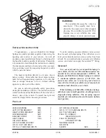
Reviews: