30
· unmatched wire feed rolls and wire size
· seriously worn contact tip
· seriously worn wire guide tube in the
torch
·poor quality wire
· please make sure wire feed rolls and
wire match
· replace torch contact tip
· replace the torch’s wire guide tube
· change a better quality wire
Regulator heater is not
working
· Heater connector is not well connected.
· shorted circuit in the heater
·machine auto-protection· failure heating
appliance inside the heater
·connect well the heater
· fix heater electric wire
·restart the machine back panel
over-current protector
· replace regulator
Note:
Above situations may be related to accessories, gas, environment and power supply applied by users. Please
try to improve the condition to avoid similar problems.
Warning! Blind experiment and careless repair may lead to more problem of the
machine that will make formal check and repair more difficult. When the machine is
electrified, the naked parts contain life-threatening voltage. Any direct and indirect
touch will cause electric shock, and severe electric shock will lead to death.
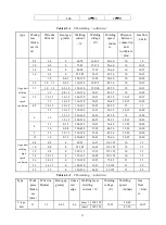
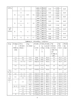
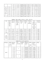
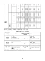
6.4 Welding processing reference (for reference only)
Welding stability, quality and productivity depend on suitable welding current and arc voltage. In order to ensure
welding quality, welding current should match arc voltage according to wire diameter, required droplet transfer form and
productivity.
6.4.1 MMA processing parameters for coated electrode
Table 6-3
Weld
posit
ion
Weldment
thickness or
welding foot
dimension
/mm
Weld of the first layer
Weld of other layers
Sealing weld
Electrode
diameter/mm
Welding
current/A
Electro
de
diamet
er/mm
Welding
current/A
Electrode
diameter/mm
Welding
current/A
Squa
re
butt
weld
2
2
55
~
60
~
~
2
55
~
60
2.5
~
3.5
3.2
90
~
120
~
-
~
3.2
90
~
120
4
~
5
3.2
100
~
130
~
~
3.2
100
~
130
4
160
~
200
~
~
4
160
~
210
5
200
~
260
~
~
5
220
~
250
5
~
6
4
160
~
210
~
~
3.2
100
~
130
Summary of Contents for MIG 350P
Page 13: ...11 4 6 2 Separated machine installation Figure 4 3 ...
Page 19: ...17 3 Operation modes Table 5 2 DC MIG operation modes Modes Sketch map 2T 4T ...
Page 20: ...18 Repeat Spot weldin g 5 2 3 Pulse MIG 1 Synergic and Separate ...
Page 22: ...20 2T with initial crater 4T ...
Page 23: ...21 4T with initial segmen t Special 4T pro gram 4T ...
Page 40: ...38 7 Wiring Diagram ...
Page 42: ...40 ...


