UMG 96-PA
www.janitza.de
26
7. 5. 2 Direction of the current
The current direction can be individually cor-
rected on the device or via the serial interfac-
es for each phase.
In the case of incorrect connection, the cur-
rent transformer does not need to be subse-
quently reconnected.
7. 5. 3 Total current measurement
If the current measurement takes place via
two current transformers, the total transform-
er ratio of the current transformer must be
programmed on the device. Setting the cur-
rent transformer ratios is described in Section
„Messwandler“.
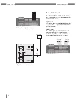
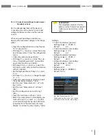
Example:
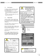
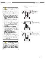
The current measurement is performed via
two current transformers. Both current trans-
formers have a transformer ratio of 1000/5 A.
The total measurement is then carried out
with a total current transformer 5+5/5 A .
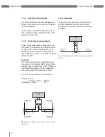
The device must then be set as follows:
Primary current:
1000 A + 1000 A = 2000 A
Secondary current:
5 A
UMG
S
2
I
S
1
P
1
P
2
Einspeisung 1
Supply 1
Einspeisung 2
Supply 2
1P
1
1P
2
(K)
(L)
(k)
(l)
1S
2
1S
1
1S
1
1S
2
2S
1
2S
2
2S
1
2S
2
(k)
(l)
(K)
(L)
2P
1
2P
2
Verbraucher A
Consumer A
Verbraucher B
Consumer B
Fig. Example of voltage measurement via a total current
transformer
7. 5. 4 Ammeter
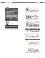
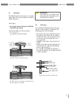
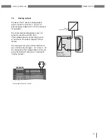
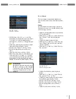
If you want to measure the current not only
with the UMG but also with the ammeter,
the ammeter must be connected in series to
the UMG.
UMG
S
2
I
S
1
Einspeisung
Supply
Verbraucher
Consumer
A
(k)S
1
S
2
(l)
P
2
(L)
(K)P
1
Fig. Circuit diagram with additional ammeter connected
in series
Summary of Contents for UMG 96-PA
Page 7: ...www janitza de UMG 96 PA 7 ...
Page 67: ...www janitza de UMG 96 PA 67 ...
Page 81: ...www janitza de UMG 96 PA 81 ...

