UMG 96-PA
www.janitza.de
46
13. 3
Frequency measurement
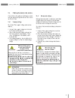
To perform this measurement, the device
requires the network frequency, which can be
either supplied by the user or automatically
determined by the device (cf. Section "Con-
figuration").
• The device can only determine the network
frequency if there is a voltage L1-N great-
er than 20 V
eff
(4-wire measurement) or a
voltage L1-L2 greater than 34 V
eff
(3-wire
measurement) at the voltage measurement
input V1.
• The network frequency needs to be within
the range of 45 Hz to 65 Hz.
• If the measurement voltage is not suffi-
ciently high, the network frequency can-
not be determined, and subsequently no
measurement can be performed.
More information can be found in Section 12
Configuration / Rated frequency
"
13. 4
Rotary field direction
Check the direction of the voltage rotary field
on the measurement value display of the
device.
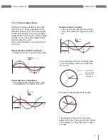
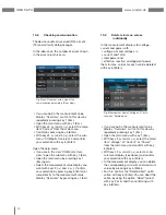
• A "right" rotary field is usually available.
UL1-UL2-UL3 = right rotary field
UL1-UL3-UL2 = left rotary field
Fig. Presentation of the phase sequence
according to the rotary field direction.
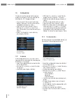
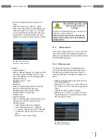
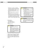
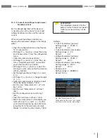
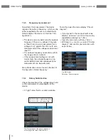
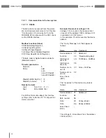
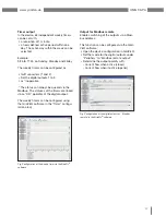
To do this, open the menu display "
Phasor
diagram
":
• If you are
not
in the measurement value
display "
Overvie
w," switch to this view by
repeatedly pressing key 1 (Esc).
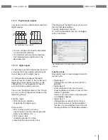
• Open the main menu with key 1 (Esc).
• With keys 3 (
) and 4 (
), select "
Pointer
diagram
" and confirm your selection with
key 6 (Enter).
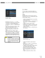
Fig. Main menu,
Selection "Phasor diagram"
Summary of Contents for UMG 96-PA
Page 7: ...www janitza de UMG 96 PA 7 ...
Page 67: ...www janitza de UMG 96 PA 67 ...
Page 81: ...www janitza de UMG 96 PA 81 ...

