


Chapter 11
– Luminous / Radiant Flux
102
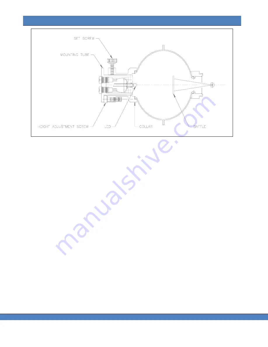
FIGURE 85
– IS-730 INTERNAL VIEW
I
NSTALLING THE
IS-730
1. Remove the current optical accessory from the PR-7XX by turning counterclockwise.
2. Install the IS-730 by carefully threading clockwise into the C mount ring located in the front of the
instrument. Make sure the threads turn freely when installing the IS-730.
M
OUNTING THE
LED
1. Loosen the Set Screw (see Figure 85) by turning it counterclockwise.
2. Remove the Mounting Tube from the Collar by gently pulling away from the sphere. If there is any
resistance, further loosen the Set Screw.
3. Insert the leads of the LED into the two miniature sockets located on the interior end of the Mounting
Tube. Push the LED in as far as possible. Take care to note the polarization of the leads. For
simplicity, the POSITIVE LEAD should be inserted into the socket corresponding to the RED Banana
Jack located on the opposite end of the Mounting Tube.
A
DJUSTING THE
M
OUNTING
T
UBE
H
EIGHT
1. Referring to Figure 86
– IS-730 HEIGHT ADJUSTMENTposition the tip of the LED so that it is directly
adjacent to the Height Adjustment Screw, and resting on the outside surface of the Collar.
2. Adjust the Height Adjustment Screw so that it is just touching the end of the Mounting Tube next to the
LED.
3. Attach the LED current source (not supplied) to the Mounting Tube using appropriate miniature banana
plugs paying attention to the polarity.
4. Supply the appropriate current to the LED and allow at least 10 minutes warm-up. Make sure the LED
is properly lit.
5. Insert the Mounting Tube into the Collar until the Mounting Tube just touches the top of the Height
Adjustment Screw.
6. Tighten the Set Screw to hold the Mounting Tube in place.
DO NOT OVER TIGHTEN!
Summary of Contents for Photo Research SpectraScan PR-7 Series
Page 2: ......
Page 10: ...PR 7XX User s Manual vi...
Page 32: ......
Page 84: ......
Page 91: ...Chapter 7 File Settings 87 FIGURE 73 ILLUMINANCE LUMINANCE CONCEPT...
Page 92: ......
Page 102: ......
Page 108: ......
Page 117: ...Chapter 12 Connectivity 113...
Page 118: ......


