STÖRUNGSERKENNUNG
PUMPE LIEFERT KEIN WASSER:
Pumpe nicht mit Wasser gefüllt; Geschlossenes Ventil in der Saug-
oder Ablaßleitung; Saug- oder Ablaßleitung verstopft; Luft gelangt in den Ansaugteil Flügelrad ver-
stopft.
LUFTBLASEN IM EINLASSBEREICH:
Luft gelangt am Anschluß in die Ansaugleitung; Siebdeckel
nicht luftdicht verschlossen; Verstopfung in der Saugleitung; Niedriger Wasserspiegel im Becken.
GERINGE PUMPENLEISTUNG:
Stellung des Wahlventils überprüfen; Teilweise geschlossenes Ven-
til in der Saug- oder Ablaßleitung; Saug- oder Ablaßleitung teilweise verstopft; Saugoder
Ablaßleitung zu klein; Pumpe läuft zu langsam (siehe oben); Verstopfter Korb im Abzug oder
Fusselsieb; Schmutziges Filter; Flügelrad verstopft.
NIEDRIGER PUMPENDRUCK:
Stellung des Wahlventils überprüfen; Pumpe läuft zu langsam (siehe
oben); Ablaßventil oder Einlaßarmaturen zu weit geöffnet; Luft gelangt in den Ansaugteil;
Flügelrad verstopft.
PUMPENDRUCK ZU HOCH:
Ablaßventil oder Einlaßarmaturen zu weit geschlossen; Rücklau-
fleitungen zu klein; Filter schmutzig.
PUMPE UND MOTOR LAUT:
Verstopfter Korb im Abzug oder Fusselsieb; Defekte Motorlager; Ven-
til in der Ansaugleitung teilweise geschlossen; Ansaugleitung teilweise verstopft; Schmutzsauger-
schlauch verstopft oder zu klein; Leitungen belasten das Pumpengehäuse; Flügelrad schleift am
Pumpengehäuse.
SAND ZURÜCK IN DAS BECKEN:
Sand zu klein; Zu starke Strömung; Sandbett kalzifiziert;
Beschädigte Ansatzstücke; Beschädigter Verteiler; Standrohr ist lose; Zuviel Sand; Einstellungss-
cheibe nicht eingestellt; Luftansammlung im Filter.
SAND LÄUFT AUS DEM REEXTRAKTIONSSCHLAUCH:
Kein Rückfluss-Adapter/keine Rückflussdüse;
Zu starke Strömung; Zuviel Sand im Behälter.
UNZUREICHENDE FILTERUNG:
Schmutziges Ansatzwasser; Ungeeigneter Sand; Unzureichende Sand-
menge; Algen im Filter; Zu stark verschmutztes Becken; Kalzifiziertes Sandbett; Hohe Anzahl von
Schwimmern; Zu starke/zu niedrige Strömung; Rückwaschzyklus zu kurz; Rückwasch-Adapter nicht
an der richtigen Stelle; Rückwasch-Anschluss zu klein.
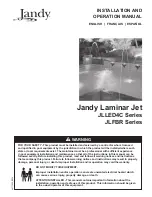
MODEL
A
B
C
D
E
L140C-7
660 mm
698 mm
812 mm
355 mm
330 mm
L160C-7
667 mm
730 mm
838 mm
406 mm
330 mm
L190C-7
711 mm
775 mm
883 mm
483 mm
318 mm
L192C-7
762 mm
826 mm
933 mm
483 mm
318 mm
L225C-7
781 mm
845 mm
952 mm
572 mm
292 mm
L250C-7
864 mm
927 mm
1035 mm
635 mm
342 mm
Abb. 6 -
Frei stehende Sandfilter Dimensionen
Einlauf
Sadfüllstand
MODELL
Rücklauf
16
3
level of the pool because this will reduce the priming time. Arrange the pipe to rise
continuously toward the pump to prevent high spots that could form air pockets. For
convenient servicing of the equipment, install gate valves in the pump suction and
pool return lines close to the pump system. These valves are recommended if the
equipment is installed below deck. Keep the gate valve in the suction line fully open
during operation. Take care during installation to keep the pipes clean and make
sure that the suction system is absolutely airtight. Only Teflon tape should be used
when connecting the pipes to the pump.
ELECTRICAL CONNECTIONS :
Check that the information on the name plate of the
electric motor corresponds to the power supply. Employ a competent electrician to
do the wiring installation.
Install an easily accessible on/off switch to turn the pump
on and off. CLREN pumps are complete with a 3 m grounded power cord and must
be connected to a grounded receptacle protected by an earth-leakage circuit
breaker with a rated trip current not exceeding 30 mA.
The wire covering must not be lighter than a flexible wire with rubber covering
bearing the symbol HO5RN-F.
Acoustic pressure less than 70dB(A).
DO NOT USE AN EXTENSION CORD! PROTECT THE CORD
FROM ABUSE BUT DO NOT BURY IT.
OPERATION
Note :
Numbers in brackets refers to key number in Figure 1.
STARTING UP :
If the pump is supplied as part of a complete filter system, follow the
starting-up procedure described in the separate instructions for the complete filter
system. In other cases, proceed a follows :
1. Close the gate valves in the suction and return lines. Remove the strainer cover
(5) from the hair and lint strainer and fill the pump completely with water. Replace
the cover.
CAUTION : Do not over-tighten the strainer RING-LOK
TM
(6); hand- tighten only.
DO NOT RUN THE PUMP WITHOUT WATER BECAUSE LACK OF WATER CAN
DAMAGE THE SHAFT SEAL. FILL PUMP WITH WATER BEFORE STARTING.
2. Open the gate valves in the suction and return lines and start the pump. if the
pump fails to produce a full flow of water within four or five minutes, switch off the
power and repeat Step 1. If the pump still fails to work, check for air leaks at the strainer
cover (5), suction line connections, and valve stem glands before repeating Step 1.
CAUTION : DO NOT OPERATE THE PUMP WITH CLOSED SUCTION OR DISCHARGE
VALVES.
3. After about ten minutes of operation, check the pool return fittings for air bubbles.
A continuous flow of air indicates leaks in the suction line. Locate and correct any
leaks immediately.
CAUTION : DO NOT RE-TIGHTEN STRAINER RING-LOK
TM
(6) DURING OPERATION.
CONTROLLING THE OUTPUT :
Keep the gate valve in the suction line fully open
during operation. Should it be necessary to control the output, use a valve in the
return line.
CLEANING THE HAIR AND LINT STRAINER :
Switch off the power. Close the valves
in the suction and return lines. Unscrew strainer RING-LOK
TM
(6) counter clockwise
and remove the strainer cover (5) from the hair and lint strainer and lift out the
strainer basket (3). Clean and replace the basket. Take care to seat the basket prop-
erly. Clean the O-ring (4) and O-ring seats on the cover and strainer. Refit the cover
and strainer RING-LOK
TM
(6), hand-tighten only, and open the valves. Put the pump
back into operation.
DRAINING :
Remove the two drain plugs (2). Note that the valves in the suction and
return lines must be open to allow complete draining of the pump. Other provisions
may be necessary for draining the filter, heater and pipe lines.
DURING PERIODS WHEN THE PUMP IS NOT IN USE, AND
ALWAYS DURING SERVICING, SWITCH THE ON/OFF SWITCH TO OFF AND PULL
THE PLUG FROM THE RECEPTACLE.
Series CLREN Pumps
Installation, Operation
THIS MANUAL MUST BE READ BEFORE INSTALLING THE PUMP
AND SHALL BE LEFT WITH THE USER OF THE EQUIPMENT
PUMP PERFORMANCE
Max. Capacity :
Max . Pressure :
Power :
Pump Model :
(m
3
/h)
(m)
(W)
C3LREN-S2
12
11
375
C5LREN-S2
13
12
450
C7LREN-5-S2
13
12
450
C7LREN-S2
17
12
600
C1LREN-5-S2
13
12
550
C1LREN-7-S2
17
12
600
C1LREN-S2
19
14
900
C15LREN-7-S2
17
12
600
C15LREN-1-S2
20
14
1000
IMPORTANT INSTALLATION REQUIREMENTS
• Install the pump in an area where flooding cannot occur.
• Attach the pump with screws to its supporting surface.
• The installation should be done so that easy access to the connection
box is provided.
• The electrical installation should be done by a licensed electrician.
• The CLREN pump is supplied with a 3 m power supply cord and plug. Connect
the plug to a grounded receptacle protected by an earth-leakage circuit breaker
with a rated trip current not exceeding 30 mA.
• The terminal box cover must be closed and tightened properly.
DO NOT USE AN EXTENSION CORD.
Caution : In order to prevent injury, a damaged power cable must be replaced
either by the manufacturer, an after-sale service technicien or any other qualified
person. Inspect the cord annually.
Power supply for all CLREN pumps : 1~, 230V, 50Hz
GENERAL
This product has been carefully inspected and packed at our factory. As the carrier
has assumed full responsibility for its safe arrival, any claim for damage to the
shipment, either visible or concealed, must be made on the carrier..
This is a
self-priming pump, which means that it can raise water through a dry suction line
without using valves, provided the pump case and strainer body are full of water
before the motor is started. Nevertheless, we recommend the use of a swing check
valve in the suction pipe, at or below water level, if the suction lift is more than 1,5 m
or if the dry suction line is more than 3,05 m long. This arrangement makes the initial
priming easy, and then keeps the suction pipe primed at all times.
INSTALLATION
CAUTION : Special installation requirements may exist for the installation of the
pump at a swimming pool or pond. Check with your local authorities. The in-
stallation must comply with local codes.
LOCATION :
Pump should be installed in accordance with the standards and
instructions in effect in your country or municipality, preferably in a dry, shaded,
and well-ventilated area. In case of doubt, please contact your retailer. Install the
pump at or below deck level. If this is not possible, choose the lowest possible
elevation, but ensure that the pump is not exposed to any possible flooding. This
simplifies priming, and adds to the pressure developed by the pump. Prepare a hard,
level surface that is large enough to accommodate the pump and the associated
equipment. Bear in mind the following : Drainage of the filter room or pit; Ventilation
of the motor; Access for servicing and winterizing the equipment; Protection of the
equipment from the elements.
PIPING :
The pump connections have female 1-1/2" NPT threads. Keep the piping as
simple as possible and keep as much of the suction pipe as possible below the water
WARNING!
WARNING!
To see the list of our europeen distributors:
http://www.competition-pool.com/distribution