7
PLEASE READ THE INSTRUCTIONS CAREFULLY BEFORE
INSTALLING
IMPORTANT
Please ensure that you thoroughly check the product upon receipt
since we cannot accept responsibility for any damage reported
after installation. Should you find any damage, please immediately
notify the forwarder.
WE RECOMMEND CHECKING THAT ALL THE ARRANGE-
MENTS COMPLY WITH THE INSTRUCTIONS FOR PRE-IN-
STALLATION.
Using protective gloves, remove the tub from the packaging, lift-
ing it only by the edge.
Remove the protective film and check for any defects. The
guarantee is not valid after installation in the event of dam-
age caused by blows or abrasion.
Preliminary operations
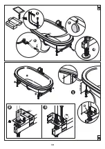
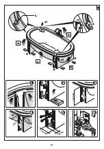
Anima Design can be installed in the centre of the room (in
which case it is equipped with panels, (
1
) or built-in (
1a
).
(
2-2a
) After removing the two front and two side panels,
place the tub in its installation location, level it (by turning the
feet) and check that:
- in models with panels
the distance from the wood skirt to
the floor
is about 50 cm (
2
).
- in built-in models, the distance
from above the edge of the
tub to the floor
is about 60 cm (
2a
).
Make sure that the feet under the tub rest firmly on the floor.
DO NOT TURN THE LOCKING NUT (G) OF THE FRAME.
Now lock each perimeter foot in place using the lower nuts
(
3
, detail 1
).
Mark the position of the 2 perimeter feet. Move the tub, and
drill one hole per foot at the marked position. Insert the plas-
tic plugs.
Assembly of tap fixture
(if included)
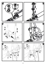
Take the box that holds the various components of the taps
and fittings.
NOTE: assembly of the taps and fittings should be done
with the tub outside of the place of installation and before
it is fastened to the floor.
(
4
) (1) Unscrew the headless screw. Slide out the
cylinder of the tub filler(2);
(3) then tighten ring nut “A” and ring
nut “B”, and afterwards install the gasket “C”.
NOTE: keep the headless screw.
(
5)
F
rom under the tub edge, insert the cylinder in the
indicated hole and tighten the coupling from above with the o-
rings.
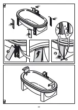
(
6
)
(1) By means of the coupling and therefore the ring
nut (2),
temporarily
fasten the cylinder.
(
7
)
Install on a tap the same units used for the cross cylin-
der. Repeat the operation for the other tap.
(
8
)
From under the tub edge, insert the taps in the indi-
cated holes and tighten from above the ring nuts with the o-rings
(
9
)
By means of the respective ring nuts temporarily fas-
ten the taps, turning one with respect to the other, so as to
make it easier to install the flexible hoses (3).
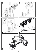
(
10
)
(1) Install the covers as shown, and fasten them from
above using the ring nuts (2).
(
11
)
Install the shower support by placing the indicated
gasket.
From beneath the tub edge, apply another gasket and attach
it with the indicated nut.
(
12
)
Take shower hose (fittings 1/2”-3/8”) and insert
them in the following components (from the side of the 3/8” fit-
ting):
button E - ring nut F - rosette G - threaded tube H - Teflon
washer I
(internal ø 2
3
.
3
mm)
- threaded tube J - spring K
- Teflon washer L
(internal ø 26 mm) -
gasket M
(the brass
part must face downwards).
(
1
3
)
Fasten the flexible hose of 1/2” M-F (provided) to
the cross cylinder and run it through the inside of the shower
support, placing it over the tub edge.
(
14
)
(1) From above the tub edge, connect the shower
hose to the hose you just installed, placing the gasket. (2) Line
up washer L and gasket M inside the shower support.
(
15
)
Screw the threaded tube J all the way into the show-
er support.
(
16
)
(1) Tighten washer I onto threaded tube H and place
the latter on spring K inside the threaded tube J (2).
(
17
)
Place rosette G in contact with the tub. Then screw
on ring nut F and finally button E on the threaded tube H.
(
18
)
Run the flexible hose under the tub edge and screw
in the shower head, placing the filter.
Summary of Contents for AnimaDesign
Page 2: ......
Page 3: ...Italiano 4 English 7 Fran ais 10 Deutsch 23 Espa ol 26 29 AnimaDesign Index...
Page 13: ...13 189 190 99 100 60 1 99 189 60 1a...
Page 14: ...14 50 cm G G 2 60 cm G G 2a 2 1 4 5 3 3...
Page 15: ...15 7 8 1 2 3 9 1 2 6 1 3 2 A B C 4 5...
Page 16: ...16 1 2 10 2 1 3 4 H I F G E J K L M 11 12 L M 2 1 13 14 1 J J 2 15...
Page 17: ...17 1 2 3 1 2 3 20 21 1 M5x5 mm 2 19 45 1 3 2 18 H H I K J H I 2 2 1 16 G H F E 17...
Page 18: ...18 1 2 3 22 23 1 2 3 24 25 3 2 1 26...
Page 19: ...19 333 mm D 1 2 3 28 2 3 4 1 27...
Page 20: ...20 a a1 d1 a2 d 1 2 d2 a1 a2 29 3 b c 2 1 4 30...
Page 21: ...21 150 mm 48 mm 90 c b a d a1 a2 d2 d1 493 mm 1 2 4 5 6 3 a1 a2 90 90 L 31...
Page 22: ...22 1 2 r s s1 r1 32 33...
Page 31: ...31 1 d 30 1 2 b 3 31 1 2 5 a2 a1 L 2 3 b c 4 5 6 d 32 1 2 r1 r 2 s s1 33...


